

Related VCF 9.0 Networking Posts:
- Self-service networking with Virtual Private Clouds
- VPC Distributed Network Connectivity – No NSX Edge VMs
- VPC Centralized Network Connectivity – With Guided Edge Deployment
- Virtual Private Clouds (VPCs) in vCenter
A Virtual Private Cloud (VPC) uses two main building blocks:
- Subnets – virtual Layer-3 networks
- Gateways – virtual routers
Every VPC owns its own VPC gateway, which routes packets between its subnets. Inside one project, a Transit Gateway links all VPC gateways together.
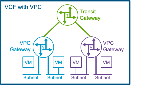
All of these virtual devices ride on the NSX fabric that VMware Cloud Foundation (VCF) installs automatically, so you can spin them up without touching the physical switches or routers.
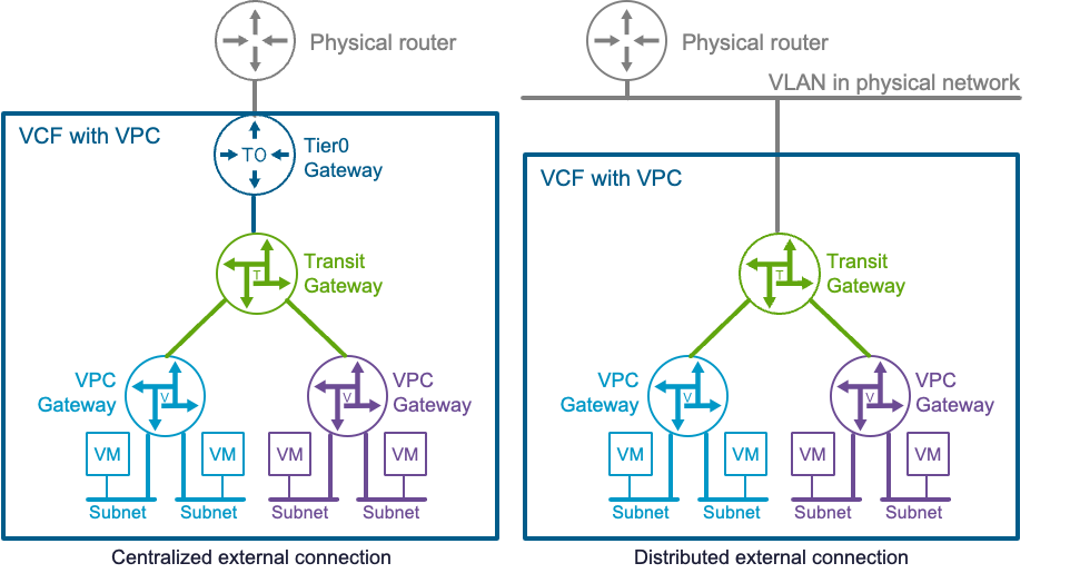
Yet many workloads still need to talk to the outside world. After you finish the VCF deployment, an enterprise admin can attach the virtual network to the physical network in two ways:
| Option | How It Works | Notes |
| Centralized external connection | The Transit Gateway forwards traffic to a Tier-0 gateway, a virtual router instantiated (centralized) on NSX Edge VMs. | All traffic in or out goes through those Edge VMs. |
| Distributed external connection (new in VCF 9.0)→ This post details this option | The Transit Gateway maps straight onto a VLAN that all ESX hosts share (distributed across ESX hosts.) | No Edge VMs or Tier-0 gateways. |
Distributed External Connection
VCF 9.0 lets the VPC fabric reach the physical network without any NSX Edge VM. You skip the Tier-0 setup and cut the workflow down to a few clicks, but you must meet one hard requirement:
Every ESX host must attach to the same VLAN on the physical network.
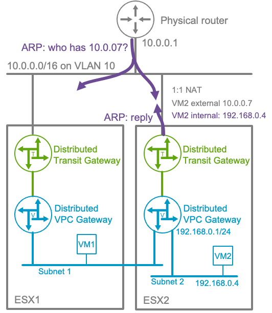
The diagram below uses the smallest possible setup:
- VM1 and VM2 sit on two private subnets in the same VPC. A private subnet is using an IP block that is not advertised outside the VPC.
- The VMs run on different ESX hosts.
- Both hosts uplink into VLAN 10. A physical router on that VLAN owns 10.0.0.0/16 and acts as default gateway.
- NSX treats addresses in 10.0.0.0/16 as a pool of “public” IPs that it can hand out to VMs that need external access.
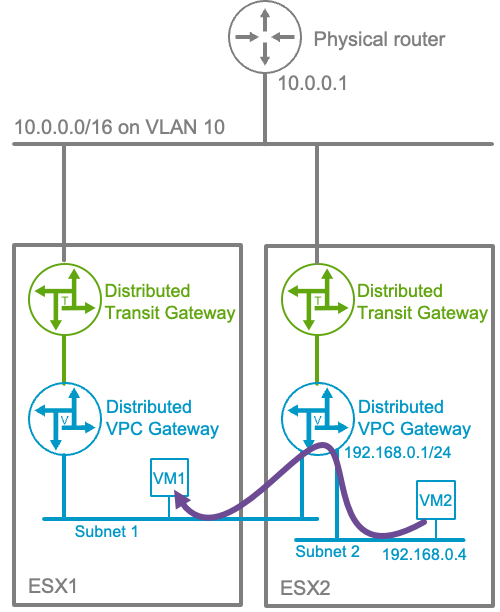
Internal traffic
The VPC gateway runs in a distributed fashion on every ESX host. When VM2 sends a packet to VM1, as represented above:
- The local VPC gateway on ESX2 routes the packet from subnet-2 → subnet-1.
- NSX encapsulates the packet and tunnels it over the overlay to ESX1.
- ESX1 decapsulates the packet and delivers it to VM1.
- Replies follow the same path in reverse (except that the VPC gateway on ESX1 routes the packets to subnet-2 before tunneling them to ESX2.)
All of this stays inside the NSX overlay; VLAN 10 is not used.
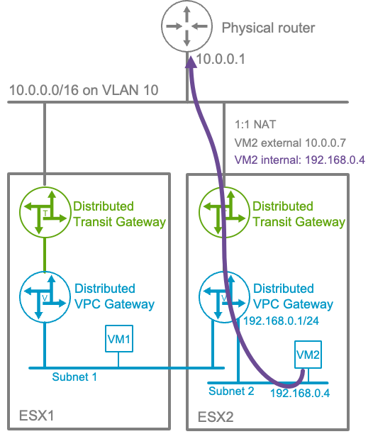
Traffic to an external destination
VM2 lives on a private subnet, which means that its IP address 192.168.0.4, is an address the physical network cannot see (private subnets are not advertised beyond the VPC.) The admin must mark VM2 as “external-facing” and assign it an external IP. When doing so, NSX reserves 10.0.0.7 as the external address of VM2 from the 10.0.0.0/16 pool.
When VM2 sends traffic destined to the outside world:
- The traffic is routed by the VPC gateway to the transit gateway on ESX2
- The transit gateway performs 1-to-1 NAT:
- Source 192.168.0.4 → 10.0.0.7
- It then forwards the packet to the physical default gateway at 10.0.0.1.
Traffic from physical network towards a subnet
When an external host targets 10.0.0.7:
- The physical router knows it needs to forward the packet onto VLAN 10.
- It ARPs for 10.0.0.7.
- The distributed Transit Gateway on the current ESXi host replies with VM2’s MAC address.
- The host receives the frame, translates 10.0.0.7 → 192.168.0.4, and routes it to VM2.
If vMotion moves VM2 to another host, the Transit Gateway on that host sends a gratuitous RARP so the physical switches update their MAC address tables.
Public subnets
A VPC can also create public subnets. In that case NSX carves the subnet IP block straight out of the external pool. For example here, “public subnet” might receive 10.0.1.0/24 from 10.0.0.0/16.

Because VM2 then owns an address (here 10.0.1.4) inside the external IP block 10.0.0.0/16, the Transit Gateway no longer needs to translate it with NAT. The gateway simply forwards packets in both directions.
Configuration in vCenter
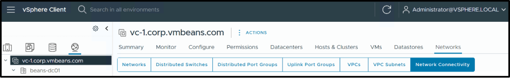
VCF 9.0 introduces the capability for configuring VPC straight from vCenter. In the network tab, select “Networks” and you’ll see VPC configuration options (“VPCs”, “VPC Subnets” and “Network Connectivity”).
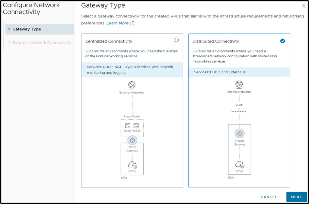
Select “Network Connectivity” and you’ll be offered the option to create a centralized or distributed connection:
Select distributed connectivity and you’ll get the following dialog box:
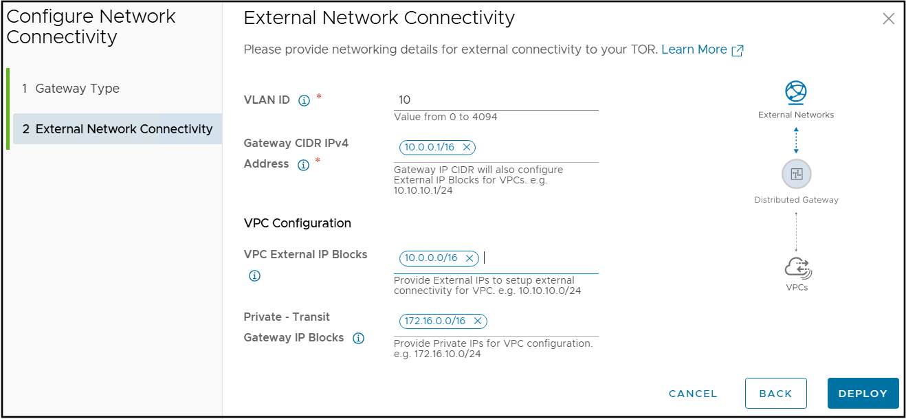
Fill in:
- VLAN ID and Gateway CIDR – match the physical VLAN and its subnet.
- VPC External IP Blocks – ranges NSX uses for external IPs or public subnets (in the case of a distributed external connection, it’s most likely the whole subnet configured on the VLAN above.)
- Private – Transit Gateway IP Blocks – Those blocks will be used when creating Private Transit Gateway subnets. You can safely use an RFC 1918 subnet.
Click “DEPLOY” and VCF can now route directly between VMs and the physical network—without any NSX Edge VMs.
Demo:
Additional details
ESX hosts are configured by VMware Cloud Foundation (VCF) with Tunnel Endpoints (TEPs) to enable overlay tunnel connectivity between hosts. The uplinks used for TEP traffic are also leveraged to reach the VLAN associated with the distributed external connection.
The distributed external connection model supports only distributed network services, such as stateless 1:1 NAT and a distributed DHCP implementation. The table below outlines the features supported in this deployment model:
| Distributed External Connection | |
|---|---|
| External IP (1:1 NAT) | |
| NAT (SNAT/DNAT) | |
| VPC Default Outbound NAT | |
| Distributed DHCP (no DHCP-Relay support) | |
| E/W Firewall | |
| N/S Firewall | |
| NSX LB L4-VIP for Supervisor/VKS | |
| Avi Load Balancer VPC Plugin |
Discover more from VMware Cloud Foundation (VCF) Blog
Subscribe to get the latest posts sent to your email.


