

Related Posts:
- Self-service networking with Virtual Private Clouds
- VPC Distributed Network Connectivity – No NSX Edge VMs
- VPC Centralized Network Connectivity – With Guided Edge Deployment
- Virtual Private Clouds (VPCs) in vCenter
A Virtual Private Cloud (VPC) uses two main building blocks:
- Subnets – virtual Layer-3 networks
- Gateways – virtual routers
Every VPC owns its own VPC gateway, which routes packets between its subnets. Inside one project, a Transit Gateway links all VPC gateways together.
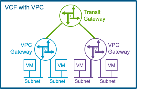
All of these virtual devices ride on the NSX fabric that VMware Cloud Foundation (VCF) installs automatically, so you can spin them up without touching the physical switches or routers.
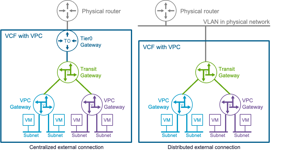
Yet many workloads still need to talk to the outside world. After you finish the VCF deployment, an enterprise admin can attach the virtual network to the physical network in two ways:
| Option | How It Works | Notes |
| Centralized external connection (new in VCF 9.0)→ This post details this option | The Transit Gateway forwards traffic to a Tier-0 gateway, a virtual router instantiated (centralized) on NSX Edge VMs. | All traffic in or out goes through those Edge VMs. |
| Distributed external connection | The Transit Gateway maps straight onto a VLAN that all ESX hosts share (distributed across ESX hosts.) | No Edge VMs or Tier-0 gateways. |
Centralized External Connection Configuration
When selecting the centralized external connection model, several key steps must be completed:
- Deploying NSX Edge VMs – These virtual appliances host the Tier-0 gateway, which connects the transit gateway to the physical network.
- Configuring the Tier-0 Gateway – This gateway enables external connectivity for the VPCs.
- Pre-provisioning IP Blocks – Required IP pools for VPC networking must be allocated ahead of time.
In VCF 9.0, a built-in wizard simplifies the first two tasks through both the vCenter and NSX Manager UIs. Below is a screenshot of the vCenter UI under the Networks > Network Connectivity tab, where you can create a centralized external connection:
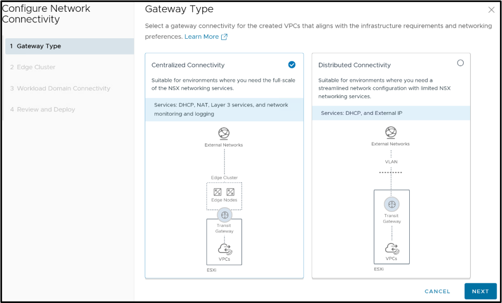
The wizard will first guide the user for creating NSX edge VMs, then guide through the configuration of the appropriate Tier-0 gateway for connecting VPCs to the external network with a centralized transit gateway.
Step 1: Deploying NSX edge VMs
NSX Edge nodes are standard VMs deployed in a vSphere cluster and grouped into NSX Edge Clusters. The guided workflow starts by creating an edge cluster, where you’ll define:
- Cluster name
- Edge VM size
- MTU for overlay traffic (information value coming from NSX – Global Fabric Settings / Tunnel Endpoint)
You then proceed to deploy your first edge VM. The wizard collects minimal input, generally grouped into two categories: Generic VM information and NSX specific information.
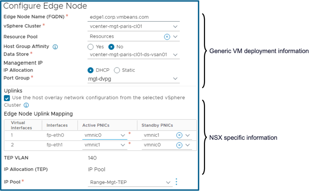
Generic VM information
This includes typical VM deployment parameters such as VM name, compute resources, and management network (e.g., mgt-dvpg). Most fields are self-explanatory and use dropdown selections. An advanced option also allows administrators to set host affinity—pinning the edge VM to a host group in the cluster.
NSX specific information
As these largely mirror NSX configurations used for ESXi hosts during VCF setup, a checkbox allows this configuration to be auto-copied for convenience.
You’ll just need to define a teaming policy, which maps logical interfaces (vNICs) to physical host uplinks (e.g., vmnic0, vmnic1).
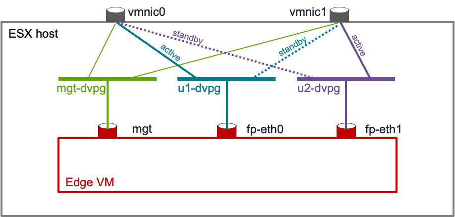
NSX edge VMs feature two types of vNICs:
- Management vNIC – Connected to the specified dvPortGroup (e.g., mgt-dvpg)
- Fast-path Ethernet vNICs (fp-eth0, fp-eth1) – These handle data-plane traffic and are connected to dvPortGroups (e.g., u1-dvpg, u2-dvpg) that are automatically created by the deployment wizard based on the teaming policy you specified.
Cloning NSX edge VMs
NSX requires at least two edge VMs per edge cluster. After configuring the first, the UI allows you to clone it easily. You’ll just need to specify unique names and management details for the additional VMs.
Step 2: Configuring the Tier-0 gateway
The transit gateway leverages the Tier-0 gateway to provide VPCs with external network access. The wizard optionally continues with Tier-0 gateway configuration, though this can also be optionally performed later.
The Tier-0 gateway is implemented as multiple Tier-0 Service Routers (SRs), each running on separate NSX edge VMs. You can deploy up to eight SRs in an active/active configuration, or opt for a two-node active/standby deployment. Each model supports different networking services and high availability characteristics.
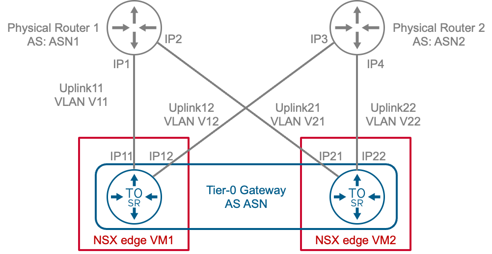
One common configuration involves deploying the Tier-0 gateway on two NSX edge VMs, each peering with a physical router using BGP (Border Gateway Protocol). Static routing is supported but is generally less flexible. The UI will prompt for the following parameters:
- ASN values – Autonomous System Numbers for the Tier-0 gateway (ASN) and external routers (ASN1, ASN2)
- Uplink configurations – Each Tier-0 SR will have uplink interfaces toward the physical routers. For those uplinks, you will need to configure:
- VLAN IDs – VLANs associated with each uplink (e.g., V11, V12, V21, V22)
- IP Addresses – for the local interfaces on the Tier-0 SR (e.g. IP11/IP12/IP13/IP14)
- BGP peer IP addresses for each uplink (e.g. IP1/IP2/IP3/IP4)
- Optional Settings – MTU values, BGP passwords, and BFD (Bidirectional Forwarding Detection) for BGP adjacencies.
Although configuration is straightforward once parameters are known, coordination with the physical networking team is essential.
Step 3: Pre-provision IP blocks for VPC
To enable networking within and outside VPCs, specific IP blocks must be pre-allocated at the project level where the transit gateway is defined. Two types of IP blocks are required:
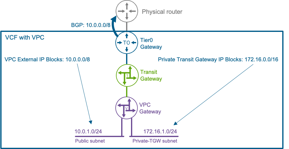
1. VPC external IP blocks
These are IP ranges owned by VCF and should not overlap with other ranges in the physical network. The Tier-0 gateway will advertise them to external routers via BGP.
Use cases include:
- Assigning IPs to public subnets (e.g., carving 10.0.1.0/24 from a broader block like 10.0.0.0/8)
- Assigning external IPs to specific vNICs requiring direct physical network access
2. Private Transit Gateway IP Blocks
Used for Private Transit Gateway subnets (e.g. 172.16.1.0/24, allocated from 172.16.0.0/16.) These IPs are not advertised externally and are scoped to the transit gateway’s project.
Centralized Transit Gateway
When configuring a centralized external connection for VPCs, the Transit Gateway (TGW) is distributed across the same NSX edge VMs that host the Tier-0 gateway. Each TGW Service Router (SR) is closely paired with a corresponding Tier-0 SR, and the deployment can be either active/active or active/standby. The selected mode directly affects the types of services that can be supported, as summarized below:
| Centralized Active/Standby | Centralized Active/Active | |
|---|---|---|
| External IP (1:1 NAT) | ||
| NAT (SNAT/DNAT) | ||
| VPC Default Outbound NAT | ||
| DHCP | ||
| E/W Firewall | ||
| N/S Firewall | ||
| NSX LB L4-VIP for Supervisor/VKS | ||
| Avi Load Balancer VPC Plugin |
Note: VCF Automation All Apps and vCenter Supervisor require Centralized Active/Standby.
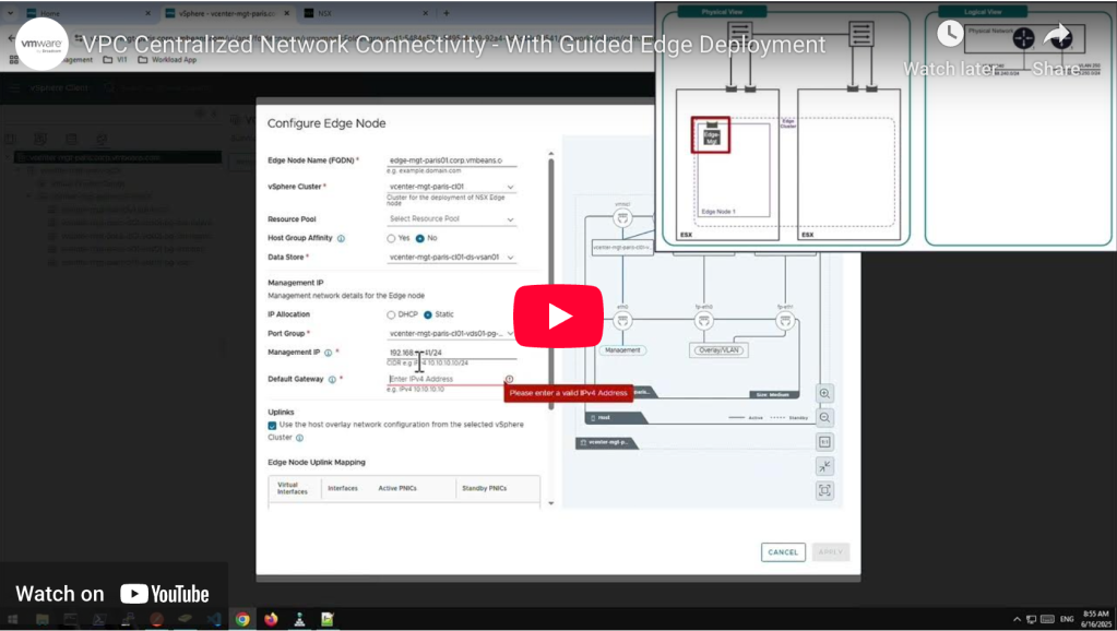
Demo : Deploying a Centralized Network Connectivity
In the demo below, you will see a step-by-step deployment of Centralized Network Connectivity:
Discover more from VMware Cloud Foundation (VCF) Blog
Subscribe to get the latest posts sent to your email.


