

vSphere has always provided several different ways to use multiple network interface card (NIC) ports together, but what is the best option for vSAN? Let’s explore some of the key points that are relevant to vSAN configurations in a network topology. The post is not intended to be an exhaustive breakdown of all potential network teaming options, but simply a reference to understand the best options available for vSAN in a VCF environment.
The concepts described here build off the information found in the posts: “vSAN Networking – Network Topologies,” “vSAN Networking – Network Oversubscription” and “vSAN Networking – Optimal Placement of Hosts in Racks.”
The Purpose of Teaming
NIC port teaming refers to a vSphere configuration that uses more than one NIC port as a resource for one or more responsibilities, such as VM traffic, or VMkernel traffic like vMotion, or vSAN. Teaming attempts to achieve one or both of the following:
- Redundancy. Provide resilience in the event of a failure of a NIC port on a host, or a switch connecting to a NIC port on a host.
- Performance. By distributing the same traffic across more than one link, it can provide some form of aggregation of bandwidth that potentially improves performance during normal operating conditions.
This post is going to focus on the topic of teaming for performance.
Common Teaming Options
The desired teaming option for vSAN depends somewhat on your environment and preferences, but there are important tradeoffs on these options that are especially relevant to vSAN. As of vSAN 8 U3, vSAN supports the use of one VMkernel port per host tagged for vSAN traffic. When using a single VMkernel port tagged for vSAN traffic, here are three of the most common approaches.
- Single vSAN VMkernel port using Active/Standby configuration. This configuration uses two or more uplinks for a single VMkernel interface, where one uplink is configured as “Active” and the other(s) are configured as “Standby.” This teaming option is the most common, and the preferred configuration for all vSAN cluster deployments. It is simple, robust, and ideal for VMkernel traffic like vSAN because it provides a predetermined path, which is especially important in Clos-style spine-leaf networks. Storage traffic prefers a deterministic path for reliable and consistent communication. While this option works great for predictable traffic flows, the single VMkernel port tagged for vSAN will only use one uplink per host for vSAN traffic. It does not offer any aggregation of bandwidth. Typically, the uplink assigned as “Standby” with this VMkernel port will be assigned as “Active” with some other VMkernel port traffic type providing other services, such as vMotion, so that links are utilized efficiently under normal operating conditions.
- Single vSAN VMkernel port with two active uplinks using Load Based Teaming (LBT). This configuration uses two or more uplinks, and would choose an uplink using “Route based on Physical NIC load.” This option can be thought of as link aggregation at the hypervisor layer. It is primarily intended for use with VM port groups, not VMkernel traffic. The benefits of using this for VMkernel traffic are relatively minor and can be problematic with storage traffic as it does not provide a deterministic path for high levels of consistent storage performance. While it is currently the default for VCF, it is not recommended for VMkernel ports tagged for vSAN in vSAN HCI or vSAN storage clusters. In VCF, you can override the VMkernel port tagged for vSAN to an Active/Standby arrangement described above without issue.
- Single vSAN VMkernel port using Link Aggregation (LACP). This configuration will use two or more uplinks paired with advanced hashing to assist with balancing multiple network connection sessions across the links. This may provide some levels of improved throughput but requires configuration on the network switches and the host to operate properly. Its effectiveness will vary widely, and may introduce more traffic on the network spine. It is not as commonly used as the options above. It also has limited support as an option when using VMware Cloud Foundation.
Your version of VCF may default to a teaming policy for vSAN traffic to Active/Active using LBT. The general configuration default in VCF allowed for a VDS to accommodate a wide variety of traffic types. While it does work with vSAN, this teaming option is not optimal for performance for any type of VMkernel traffic. VMkernel ports tagged for vSAN traffic should use Active/Standby using “Route based on originating virtual port ID” for optimal performance and consistency. This is a supported configuration change in VCF and can be selected when using the custom VDS deployment option in VCF. For more information, see the “VMware Cloud Foundation Design Guide.”
Can multiple VMkernel ports per host be tagged for back-end vSAN traffic? It is possible to do so only under a very specific corner case where a pair of switches are fully air-gapped in a manner similar to a Fibre Channel fabric. This configuration is not common or recommended for standard topologies up to and including vSAN 8 U3.
Teaming and the Impact on Spine-Leaf Networks
The teaming selection used on vSAN hosts may seem like a benign choice, but it can have a significant impact on the network it is using, and the performance of vSAN. With a Clos-style spine leaf design, there may not be an interconnect between the two leaf switches. We know that if a host is using a team of two uplinks, the uplinks will be connected to the two ToR switches to ensure connectivity in the event of a switch failure. In an Active/Active LBT configuration, this means that approximately half of the traffic may traverse over the spine that would otherwise remain at the ToR leaf switches if using an interconnect. This would introduce additional latency and degrade storage performance and consistency if not accounted for in the design. The same concern would apply to LACP. LACP would also assume an interconnect between the two ToR switches, and in an environment where there is no interconnect, may traverse the traffic over the spine, or break the LACP bond entirely.
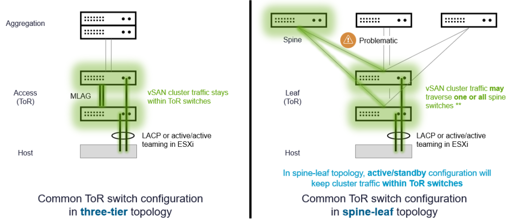
Figure 1. The impact of teaming on a spine-leaf topology.
In practice, some spine-leaf configurations have the ToR switches connected by an interconnect such as an MLAG, or VLTi. This should not be assumed, nor is it necessarily a desirable trait in a spine-leaf network since that will usually introduce blocking mechanisms like Spanning Tree (STP).
Cost and Performance of Native Link Speed versus Link Aggregation
Link aggregation for the purposes of performance can certainly be beneficial in the right circumstances using the appropriate methods. But the benefit is often misunderstood, and misused in scenarios that end up being more costly than realized. Let’s look at four commonly overlooked aspects to using link aggregation over higher native link speeds.
- High port consumption. There is a costly nature of port/link usage if you are wanting to aggregate links. This effectively lowers the port capacity of the switch, which in turn may limit the number of hosts in a rack.
- Limited performance improvement. Link aggregation options also have limitations in terms of the performance gained from algorithmic load balancing. With load balanced link aggregation like LACP, 1+1 does not equal 2. It tends to work better in conditions with a large number of data streams with limited improvement on discrete workloads.
- Misunderstandings on cost effectiveness. The conventional wisdom suggests that aging 10Gb switches are more cost effective. This is not true. One way of measuring cost effectiveness is by “switch capacity.” It is a term used to represent the amount of data a switch can process, and is typically measured in gigabits per second (Gbps) or terabits per second (Tbps) at the switch level. While the total cost of the 10Gb switch might be a little less, faster switches may offer 2x to 10x the switching capacity, making the price per Gbps lower on the faster switches. On the servers, choosing NICs faster than 10Gb will often change the cost by less than 1%, but may yield a 2.5x to 10x improvement in performance.
- Stranded resources. New servers with extraordinary amounts of CPU, memory and storage are simply unable to exploit the capabilities of the hardware because of a constrained network. A more proportional balance of network throughput paired with today’s servers may allow you to reduce the total host count, which lowers your capital expenses, server footprint, cooling, and network port consumption.
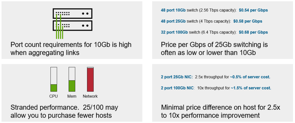
Figure 2. The hidden costs of aggregation for an old or undersized network.
It is for these reasons that we recommend choosing higher native link speeds (25Gb or 100Gb) rather than rely on some form of link aggregation – especially as it relates to 10GbE. Remember that when 10GbE became available 23 years ago, CPUs in servers consisted of a single core, and memory capacity was 1/20th to 1/40th of what it is today. With 25GbE being available for nearly a decade, the usefulness of 10GbE in the data center has largely come to an end.
Further information on vSAN networking may be found with the vSAN Network Design Guide. For VCF environments, see “Network Design for vSAN for VMware Cloud Foundation.”
Host Uplink Counts Per Host
Teaming for performance and redundancy generally assumes the use of more than one physical NIC, where each NIC may have 2 to 4 NIC ports. How many total ports should you have on your vSAN hosts? The answer typically depends on the following:
- Demand of workloads. An environment serving relatively idle VMs will not demand as much as an environment hosting complex and resource intensive applications.
- Native bandwidth of uplinks. Higher native bandwidth speed will help reduce the potential for contention of multiple services (vMotion, VM port groups, etc.) running across a team of uplinks.
- Storage services used. Typically, dedicating a pair of NIC ports for storage services will yield the best results. This has been a common practice regardless of the storage solution used.
- Security/Isolation requirements. Some environments may have security requirements that a team of uplinks be isolated from other services or tenants.
- Port count of the ToR switches. Sometimes the ToR switches may be the limiting factor in the number of host uplinks that can be used in a rack. For example, a pair of 2×32 port ToR switches would provide 64 ports to the hosts in the rack. Assuming the maximum of 16, 2U hosts per rack, this would limit each host to a maximum of 4 uplink ports per host. If there were 48 port ToR switches, this would allow 6 uplink ports to be used in each of the 16 hosts in the rack. Fewer servers per rack would also increase the number of uplink ports that could be used for each host in a rack.
Recommendation: Even if you don’t use all of the uplinks on a host, build your vSAN ReadyNodes with at least 2 NICs consisting of 4 uplink ports per NIC. This will allow you to easily use a dedicated team of uplinks for vSAN storage, which is highly recommended. It will also offer much more flexibility with current and future capabilities in vSAN than 2 NICs consisting of 2 uplink ports per NIC.
Summary
Choosing the best network teaming option and network speeds for your vSAN hosts is an important step in the ability for vSAN to deliver the very best possible performance for your workloads.
Discover more from VMware Cloud Foundation (VCF) Blog
Subscribe to get the latest posts sent to your email.


