

Since vSAN is a cluster-based solution, the placement of hosts in your network racks will impact how much traffic may traverse the spine. Traffic traversing the spine is not necessarily bad, but it should be part of a design exercise when vSAN is introduced in an environment. This post will illustrate some basic layouts of vSAN clusters in racks in an effort to minimize traffic across the spine and potentially improve performance.
The concepts described here build off the information found in the posts: “vSAN Networking – Network Topologies” and “vSAN Networking – Network Oversubscription.”
vSAN Traffic Flow as It Relates to Racks
Assuming the vSAN hosts are cabled and configured correctly, vSAN traffic will stay within the ToR switches if an aggregated vSAN HCI cluster fits within a single rack. Similar principles apply to vSAN storage clusters, but if the vSphere clusters mounting the datastore of the vSAN storage cluster are in other racks, then a subset of this traffic will traverse the spine.
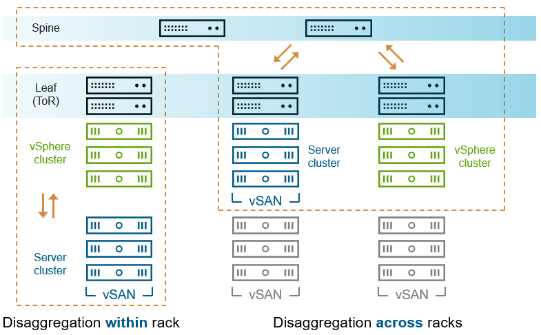
Figure 1. Relationship of vSAN designs in a spine-leaf network.
Reference Designs for vSAN Clusters in Racks
How should your vSAN hosts be deployed in your racks? The answer will depend on several factors, but the following three examples will walk you through some basic designs. The examples assume the use of 42U racks, two ToR switches in each rack, and rack-mounted 2U servers. This typically results in about a maximum of 16 hosts per rack. The configuration of the vSAN VMkernel interface on each host assumes the use of Active/Standby teaming using “Route based on originating virtual port ID”, where each active VMkernel port is cabled to the same ToR switch, and the standby port is cabled to the other ToR switch. The examples below purposely do not describe the speed of networking used, oversubscription ratios, etc, but rather focus on smart placement of hosts to transmit storage traffic efficiently.
vSAN HCI Clusters in a Row of Racks
This example demonstrates an efficient placement of aggregated vSAN HCI clusters that do not require rack level resilience. The four vSAN clusters are placed in a manner that allows each cluster to reside within a rack. This helps minimize or eliminate vSAN traffic traversing the network. Two of the vSAN HCI clusters borrow storage resources from each other courtesy of datastore sharing. In this scenario, the vSAN client traffic transmitted between the two clusters will also stay within the ToR switches.
If one of these clusters was to mount the datastore of a vSAN cluster in another rack, that vSAN client traffic would traverse the spine. In this scenario, one could possibly get away with a network oversubscription ratio of higher than 1:1, but it would be best to ensure a full line-rate bandwidth of 1:1 is available in the event that the scope of the vSAN clusters change.

Figure 2. vSAN HCI clusters in a row of racks.
vSAN HCI Clusters in a Row of Racks using Fault Domains
In this example, a vSAN HCI cluster is configured with vSAN’s “Fault Domains” feature, where each rack is defined as a fault domain. A fault domain could be considered a boundary of acceptable failure. While the fault domains feature would ensure that data would maintain availability in the event of a rack failure, it will transmit back-end vSAN traffic across the network spine. In this configuration, you will want to ensure that your network oversubscription ratio is 1:1.
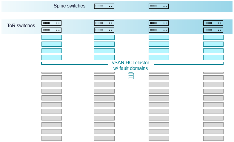
Figure 3. vSAN HCI clusters configured for rack-level resilience using vSAN fault domains.
Accounting for the bandwidth needs of this topology is shown on Figure 3 in the post: “vSAN Networking – Network Oversubscription.”
vSAN Storage Clusters in a Row of Racks
This example shows the use of a vSAN storage cluster in a row of racks. Ideally, the vSAN storage cluster would be no larger than what could fit within a single rack. This would help ensure that the back-end vSAN traffic could remain within the ToR switches. The front-end traffic communicated to and from the vSphere clusters mounting the datastore would traverse the spine. But front-end traffic to and from the client clusters mounting the datastore of the vSAN storage cluster need less bandwidth (about 1/3rd) than needed for the storage cluster. Thus, it makes most sense for the vSphere clusters consuming the vSAN datastore to reside in other racks.
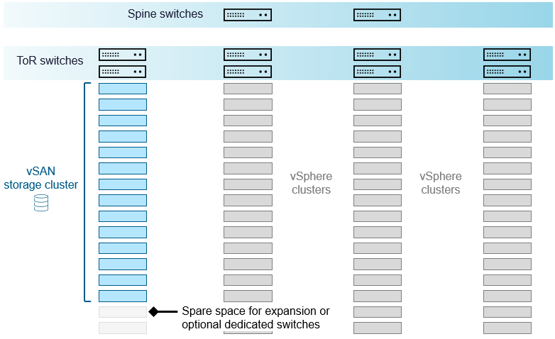
Figure 4. vSAN storage cluster in a row of racks.
Given the current capabilities of vSAN ReadyNodes certified for vSAN storage clusters, one could easily provide 4-5PB of raw storage capacity per rack. One could scale out the vSAN storage cluster if there is space remaining in the rack, or a new storage cluster can be created in a new rack. Both will be able to maintain an optimal arrangement for the network by minimizing the amount of traffic traversing the spine.
Recommendation: Unless you have specific needs to provide rack level resilience, size your vSAN HCI clusters and your vSAN storage clusters with a host count no larger than can fit in a single rack. This will help provide an optimal data path for your network traffic, and may make ongoing operations and maintenance easier.
Further information on vSAN networking may be found with the vSAN Network Design Guide. For VCF environments, see “Network Design for vSAN for VMware Cloud Foundation.”
Summary
A vSAN cluster has unique demands on a network infrastructure that may need thoughtful placement of hosts in your architecture. The examples above demonstrate some simple steps you can take to make your vSAN cluster deployment more efficient with your network.
Discover more from VMware Cloud Foundation (VCF) Blog
Subscribe to get the latest posts sent to your email.


