

Over the past year we’ve seen a surge in adoption of vSAN as the primary storage solution for VMware Cloud Foundation (VCF). This can likely be attributed to three reasons. First, customer hardware refresh cycles are enabling environments to transition to the vSAN Express Storage Architecture (ESA) which offers supreme levels of performance. We’re also seeing VCF customers revisiting vSAN given the new license model that provides 1 TiB of vSAN capacity for every VCF core licensed. Finally, the introduction of vSAN storage clusters (previously known as vSAN Max) provides an option for customers who prefer centralized shared storage, but still want to use vSAN – the storage solution built into the hypervisor
But with that surge and success comes questions, especially around networking. Regardless of how it is deployed, vSAN’s distributed architecture relies on networking for data availability, performance, and management. All storage systems rely on a network fabric, but unlike the dedicated, isolated network fabrics with traditional three-tier architectures, vSAN typically converges this storage traffic on the same network as other traffic.
Similarities and Differences with Traditional Storage
While vSAN’s approach to resilient storage is different from traditional storage, many of the principles remain the same. Whether it be Fibre Channel used with a storage array, or an Ethernet network used with vSAN, storage traffic typically needs sufficient bandwidth paired with a reliable and predictable path to deliver the performance and availability expectations required.
With a traditional storage system, the flow of traffic is fairly clear. Storage I/Os are transmitted to and from HBAs on a host to a storage array. The storage array will write the data in a resilient way across the disks in the enclosure using its internal backplane.
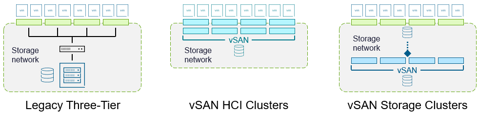
Figure 1. Comparing storage fabrics of traditional three-tier and vSAN.
Since vSAN is a distributed storage system, it must write the data across multiple hosts to ensure the data is resilient. It also performs other back-end data activity, including data rebalancing across hosts, complying with storage policy changes, host maintenance mode activities, and automatic repairs of data. These are automated activities that do not need to be of concern for an administrator, but it does require sufficient network resources to ensure that these activities can be completed in a timely manner.
With an aggregated vSAN HCI cluster, the read and write commands from the guest VM come from the same cluster as the vSAN datastore. For disaggregated deployments using vSAN storage clusters, the read and write commands from a guest VM do not come from the same cluster as the vSAN datastore, but from vSphere hosts mounting the datastore. As a result, front-end traffic to and from the client cluster requires less bandwidth than the network connectivity for the hosts that comprise the vSAN storage cluster. The proportion of back-end vSAN activity to front-end guest I/O requests can vary depending on workload characteristics and other conditions such as rebuilds, rebalancing and storage policy changes. One can estimate the back-end traffic is about 3 times the amount of front-end traffic. This amplification can be expressed as “3:1.” Another way to state it would be that the front-end traffic is about 33% of the back-end traffic. This means that your vSphere hosts mounting the datastore of a vSAN storage cluster will need less bandwidth relative to what the storage cluster uses.
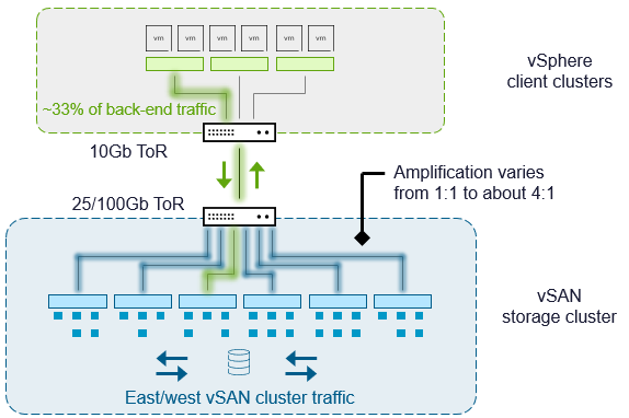
Figure 2. Understanding relationship of front-end vSAN traffic to back-end vSAN traffic.
Understanding this amplification with a vSAN storage cluster will help you understand how much bandwidth is needed across the network spine for the vSphere clusters mounting the datastore of a vSAN storage cluster residing in its own rack.
Networks can be constructed in a myriad of ways. With vSAN, the design of your network matters! How they are built may impact the ideal way vSAN should be deployed in the environment. It is not unusual for a virtualization administrator to think there is an issue with vSAN, only to find out it was actually an unknown issue with the network.
Let’s take a look at some of the common network configurations as a basis for understanding your own design decisions with vSAN. This information will apply to aggregated vSAN HCI deployments and disaggregated vSAN storage cluster deployments. It will help both the virtualization and network teams work together to understand what is needed for a reliable and consistent network for vSAN.
A Primer on Common Network Topologies
vSAN storage traffic traverses the network, which means that the network architecture will in part determine the 1.) availability of data, 2.) peak performance and consistency of performance.
The two most common network architectures are a three-tier architecture, and spine-leaf architecture. They both have a distinct way of connecting hosts in rack to each other, which can present different considerations when thinking about the design of an environment. These architectures can play a part in the availability of the data and the performance of the system.
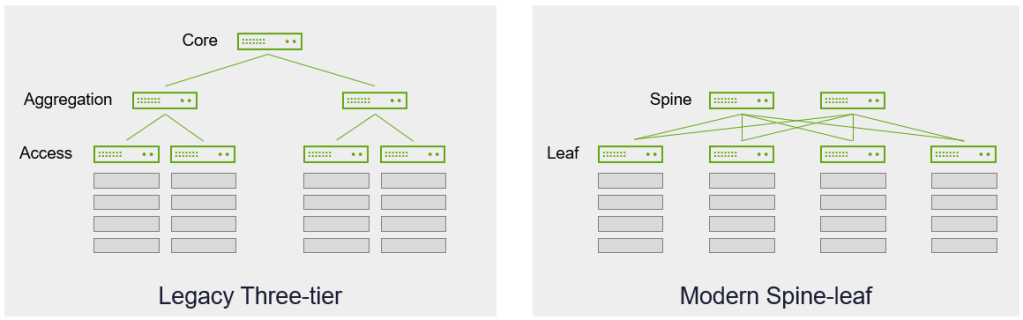
Figure 3. Common network topologies in a data center.
It is not unusual to find variations of each topology, as well the topology described only acting as a subset of an overall infrastructure. Instead of looking at a network topology in its entirety, this post will focus on how the hosts that make up one or more vSAN clusters interact with each other, and how the network topology design for these clusters can influence performance and availability.
Legacy Three-Tier Networks
A three-tier network architecture is one that consists of a core, aggregation, and access layers. It is connected in a hierarchical manner that allows for traffic to flow up and down the layers depending on the source and the destination. It relies heavily on aggregated links to provide the appropriate bandwidth upstream. Since there may be multiple paths available, it may use methods to manage these multiple paths (blocking via Spanning Tree Protocol, also known as STP, or redirection through ECMP). Three-tier architectures had a reputation for being difficult to scale, and deliver consistent performance levels. It has largely fallen out of favor for spine-leaf designs.
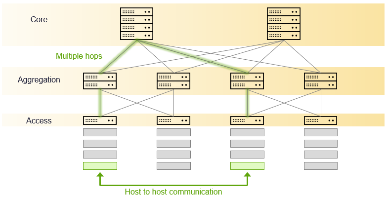
Figure 4. Legacy three-tier network topology.
Modern Spine-Leaf Networks
A spine-leaf network consists of two layers, where the leaf switches are typically at the top of a rack (ToR), and connect directly with the hosts. The spine is the backbone network, where all leaf switches connect to the spine. There are a few characteristics that offer a distinct advantage of spine-leaf over three-tier designs. One is the ability to scale out easily. Simply add more spine switches to improve connection bandwidth between leaf switches. Or add more leaf switches to support more racks and hosts. This design also offers a minimal number of network hops between any two points regardless of where the source and target are located. It is a non-blocking design, which makes it much more predictable in its performance.
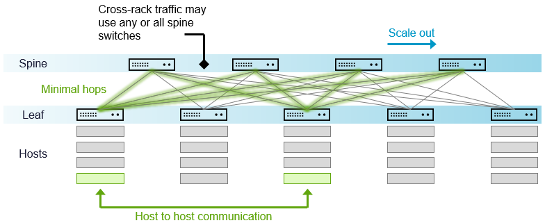
Figure 5. Modern spine leaf network topology.
Spine-leaf designs have some distinct characteristics that differ from three tier architectures. First is that all leaf switches will always have a direct connection to all spine switches. But most interesting is that there is typically not any direct connectivity from leaf switch to leaf switch, or spine switch to spine switch. This characteristic is what helps these networks avoid the use of blocking mechanisms like STP, but can have an impact on design recommendations for redundancy and aggregation. In some cases, you may find in a spine-leaf design that the two ToR leaf switches are connected with a link (MLAG, VLTi, etc). This practice, however, does not follow a true Clos-style spine-leaf architecture.
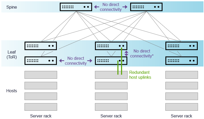
Figure 6. Additional characteristics of a true Clos-style spine-leaf design.
While an interconnect between the ToR switches in a three-tier network architecture is common, a Clos-style spine-leaf design may NOT have an interconnect between the two ToR switches. Why is this important? Imagine for a moment where you know traffic is going to be communicating between hosts in a rack, serviced by two ToR leaf switches. You may assume the traffic is going to stay within the ToR switches regardless of how the hosts are cabled. But because the uplinks are using both ToR switches, the only way to complete the connection is through the network spine.
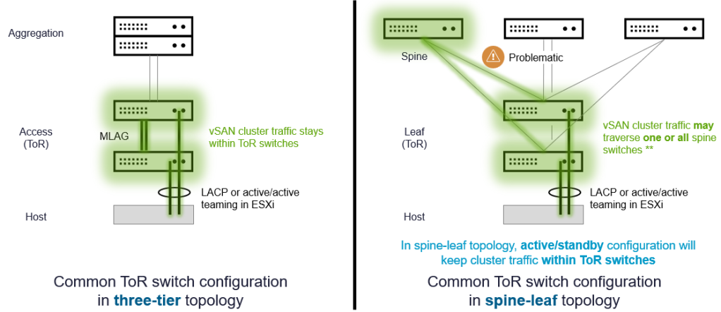
Figure 7. How teaming policies may push traffic across the network spine.
For spine leaf networks, it is important to ensure uplinks from hosts are cabled properly, and any aggregation techniques do not inadvertently transmit data across the spine.
Further information on vSAN networking may be found with the vSAN Network Design Guide. For VCF environments, see “Network Design for vSAN for VMware Cloud Foundation.”
Summary
When using a distributed storage system like vSAN, the network plays a crucial role in the ability to ensure that data is stored in a resilient and speedy manner. Understanding the network topology in your environment, and how your racks of vSAN hosts communicate across your network will help you provide storage systems with the highest levels of performance and resilience.
Discover more from VMware Cloud Foundation (VCF) Blog
Subscribe to get the latest posts sent to your email.


