In the last post I covered the configuration of one of the port mirroring session type, Switch Port Analyzer (SPAN) on a host. SPAN is a simple configuration on VDS that allows users to quickly replicate traffic to another virtual machine on the same host. However, SPAN on VDS has following limitations
– The source and destination ports of the session should be on the same host. Thus limiting the visibility to a particular host.
– If the monitored virtual machine is moved from one host to another using vMotion, you can’t monitor that virtual machine traffic anymore.
The Remote SPAN (RSPAN) port mirroring session addresses above concerns and also provides the capability to send mirror traffic to a central analyzer tool. The analyzer tool can be connected multiple hops away in a network as shown in the diagram below.
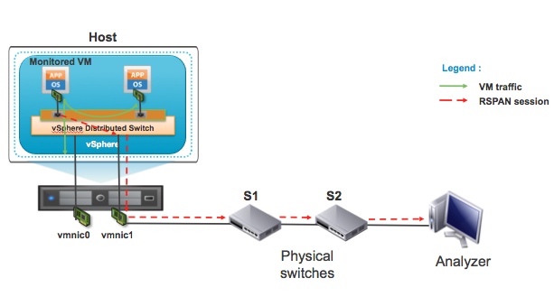
The RSPAN port mirroring session configuration is little more involved when compared to SPAN setup. You have to configure RSPAN session on VDS and also configure RSPAN VLAN on physical switches. A dedicated RSPAN VLAN is defined to carry the port mirror traffic. Let’s briefly take a look at the main components of the RSPAN session as shown in the above diagram.
1) VDS – VDS is called as source switch because RSPAN source of the port mirroring session is on this virtual switch.
2) S1 – Physical switch is intermediate switch. S1 is not RSPAN source or destination switch.
3) S2 – Physical switch is destination switch. The S2 switch port where Analyzer is connected acts as RSPAN destination.
4) Analyzer – Device where packet analysis is performed.
Since RSPAN end to end mirror session configuration requires physical switch support, users should look at the physical switch vendor’s documentation for guidelines and any limitation of RSPAN feature.
We will now go through the steps of configuring a remote mirroring (RSPAN) session on VDS. As shown in the diagram below, select “Remote Mirroring Source” and configure the source of the RSPAN session.
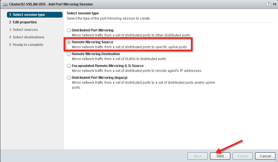
According to the configuration screen above, VDS switch can also act as the destination for the RSPAN session by selecting “Remote Mirroring Destination”. I will talk about that deployment in the part 3 of this series.
The next step in the configuration process is enabling the port mirror session status, providing VLAN ID for RSPAN traffic, and selecting or deselecting the preserve original VLAN option.

In this example we have configured VLAN 400 as RSPAN VLAN or “Encapsulation VLAN ID”. We have deselected Preserve original VLAN. Also, allow Normal I/O on distributed ports (Please refer to the diagram below).
In scenarios where virtual machine tags traffic and you want to preserve the VLAN information in the monitored packets, you should check the preserve original VLAN box. Once you check the box the mirrored packet will be double tagged also called as QinQ tag. The external tag of these packet will be VLAN 400, RSPAN VLAN. In this example the monitored virtual machine doesn’t send tagged traffic so we have deselected preserve original VLAN option.

The next step is to select the ports that need monitoring. As shown in the figure below, select the virtual machine or vmknic ports that you would like to monitor as part of this RSPAN session.
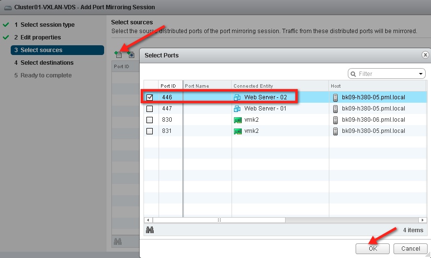
Then select the direction of the traffic that will be mirrored. In this case both ingress and egress traffic is selected.

After the source port and traffic direction config, it is time to configure the destination port where the mirror traffic will be sent. You can choose uplinks connected to the VDS as the mirror destination.

In this example, we have selected only uplink1 to carry the mirror traffic.

This concludes the configuration on the VDS.
After completing the RSPAN source session configuration on VDS, we will configure the Switch S1 and S2 such that mirror traffic is delivered to the Analyzer connected on the S2 port. Please refer to the “RSPAN Deployment” diagram for the switch connectivity details.
S1 Switch Configuration:
1) Configure VLAN 400 as RSPAN VLAN (Example Cisco CLI commands)
- Vlan 400
- Remote span
- exit
2) Configure physical switch port where host’s vmnic1 (uplink1) is connected as trunk, and then add VLAN 400 in the list of allowed VLANs.
3) Configure VLAN 400 on the trunk port connecting physical switch S2.
S2 Switch Configuration:
1) Configure VLAN 400 as RSPAN VLAN (Example Cisco CLI commands)
- Vlan 400
- Remote span
- exit
2) Configure VLAN 400 on the trunk port connecting physical switch S1.
3) Configure destination RSPAN session to send traffic to the switch port where analyzer is connected (Example Cisco CLI commands)
- monitor session 10 source remote vlan 400
- monitor session 10 destination interface Gig 1/22
After this configuration you will be able to monitor virtual machine traffic centrally on the Analyzer device that is connected multiple hops away from the source.
In the next post, I will discuss how you can configure VDS as the RSPAN destination session and monitor traffic centrally through a virtual machine connected to the VDS.
Get notification of these blogs postings and more VMware Networking information by following me on Twitter: @VMWNetworking


