

In Part 1 of this series we saw how workloads in the OCVS SDDC could use the OCI NAT Gateway to reach the Internet. In Part 2 we’ll make a few changes and allow inbound access from the Internet. We’ll also make sure we don’t break the outbound access we worked so hard to build in Part 1.
Introduction
In the last post we saw the OCI NAT Gateway providing access to the Internet and a Public IP address to hide behind. We also saw that it could only offer this service to native Oracle Cloud devices with interfaces which have OCIDs attached. We learned that even though our OCVS SDDC VMs didn’t qualify, through the External Access VIP assigned to it, the Tier-0 router did. That meant, as long as we NAT our VMs behind the T0, they could all use the NAT Gateway. Happy days!
So, how are we going to turn this all around? Let’s start with a quick picture to refresh ourselves on how we got outbound Internet to work in Part 1.
TL;DR – Just take me to the how-to!
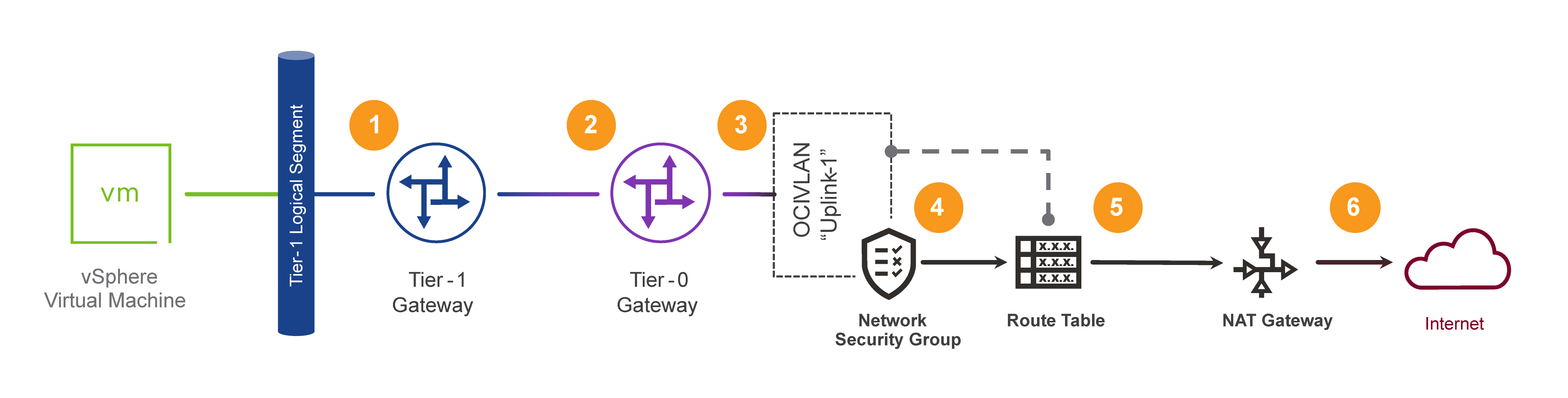
The key things to note from that image, as they apply to the topic at hand in this post are:
- In (3), we had to help the NAT Gateway find its way back to the Workload VM using the Tier-0’s VIP and its loaned Oracle Cloud IDentifier (OCID).
- In (6), we didn’t need to do anything about public IP address selection/NAT, as the NAT Gateway handled all that for us.
The NAT Gateway is good for NAT (which is probably just as well, to avoid it being sued for false representation or something) and keeping track of where its outbound connections came from. But its limitation is/was that it came with a built-in Public IP address, “a” (singular) Public IP address, which doesn’t sound like it will give us much scale. In fact, not only does it not scale, it can’t handle unsolicited inbound connections either. There’s no way to tell the poor NAT Gateway what it should do if somebody uninvited comes knocking. For that, we need its tougher sibling, the Internet Gateway.
Bring on the Internet Gateway
The Internet Gateway can handle unsolicited inbound connections. It doesn’t have its own Public IP Address to limit it, instead, the Internet Gateway just asks that any device wanting to use it should bring along its own Public Address. Here’s the list of all err… one of our Internet Gateways in the lab we stole the screenshots from in the last post.
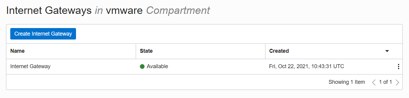
And that’s all there is to the Internet Gateway. No convenient (but limiting) Public Address, just a name and, although not shown in the UI, an OCID something like ocid1.internetgateway.oc1.loc.areallylongandhopefullyuniquestring.
OCI Inbound Internet Access
As we did in the first post, before looking at OCVS, let’s see how Inbound connectivity works in OCI.
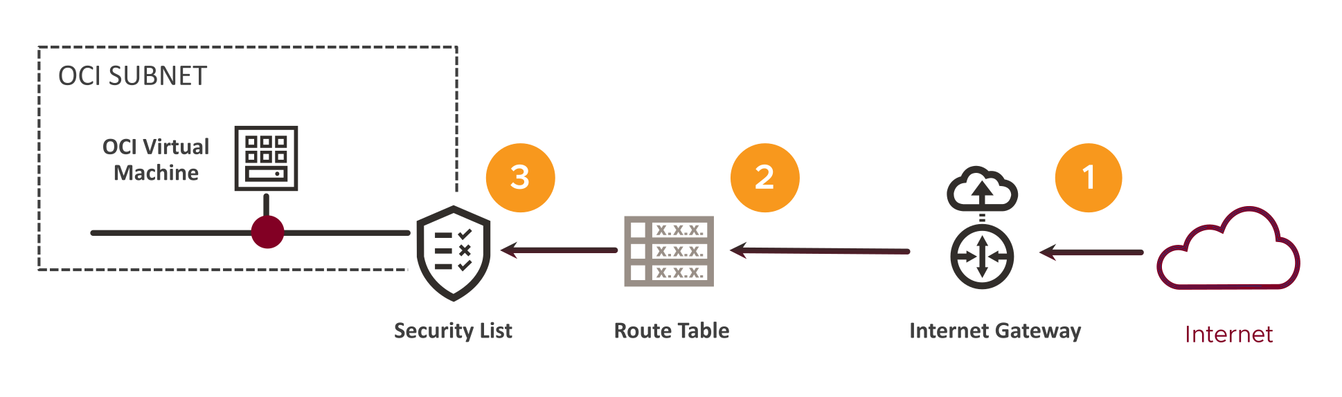
This flow is mostly the same as the Outbound Internet flow, except in reverse. In this case, in order to reach the VM we will need:
- A public IP address that gets us to the Internet Gateway.
- Routing to the Subnet where the target VM lives.
- Permission to enter the Subnet, through an entry in the Subnet’s Security List.
Let’s look at those steps in a little more detail.
- There is no IP address in the Internet Gateway, we saw that a couple of paragraphs earlier! Instead, the VM’s interface on the OCI (Public) Subnet is assigned a public address (indicated here by that Internet-red colored dot below the VM) which is used (together with / via its OCID) to allow the Internet Gateway to link the Public Address to the VM’s Private IP/OCID. This public IP address is in addition to the interface’s private address from the subnet.
- We’re not using that (now faded) Route Table to find the VM, that’s handled automatically by the control-plane. We are though (so the icon is not totally “wrong”), going to need our Subnet’s Route Table to return traffic back, to the Internet Gateway, this time…
- Oh, wait… This is okay, we are using the Subnet’s Security List in pretty much the same way as we did last time. For Inbound connections we will need an Ingress rule of course, whose Stateful nature will then allow returning traffic from the target VM. So, same list, different rule this time. I think we can still claim that as correct?
To paraphrase the first post…
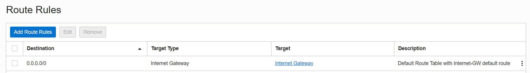
The way the Internet Gateway works is nice and simple. We use a Route Table rule, like the one below, to direct traffic heading back to the Internet using the 0.0.0.0/0 destination. We set the Target Type to “Internet Gateway” and select the Internet Gateway deployed in our SDDC. Here’s an example of a Route Rule like that, in a Route Table, targeting an Internet Gateway (which is helpfully named “Internet Gateway”).
And, if we were to deploy a VM with a Public Address assigned, or, add one to an existing VM (on a “Public” Subnet of course), it would look something like this:
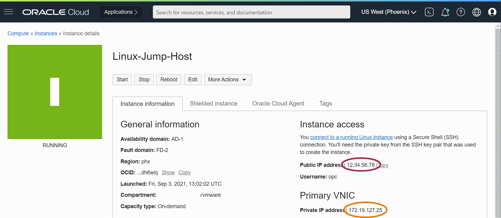
We can see the VM’s Primary “Private IP” address in the orange oval, and, above that, its “Public (Internet) IP” address in the red one. We talked about incoming connections to the Public address, but, if we originate a connection to the outside world, we’ll do so from that same public address. That will become important when we’re looking at the OCVS stuff in a few paragraphs’ time!
Okay, with that foundation covered, let’s look at the OCVS version of events!
OCVS SDDC Workloads Inbound Internet Access
As we did in the last post, let’s revisit the flow diagram above, but this time with the SDDC components added. As before, workload VM on T1 Logical Segment behind a T0 Gateway. No surprises there, or rather, here…

To reach an OCVS VM from the Internet, we’ll need:
- An Internet Gateway to handle receiving traffic for our Public Address.
- A Route Table, not so much for steering the incoming traffic, but for ensuring the outgoing traffic from our SDDC now goes via the new Internet Gateway instead of the old NAT Gateway.
- A Network Security Group (as we’re landing on a VLAN) with rules to allow ingress flows from the Internet, and egress flows to the Internet.
Now we’re heading back into the SDDC under the control of NSX-T.
- An IP address on the Uplink VLAN to target for our workload VM via the T0.
- A route from the T0 to the relevant T1.
- The VM’s workload Logical Segment connected to the T1.
We need to figure out two new pieces of the puzzle. They are, where does the public IP address come from, and how does it get associated with the target, workload, VM? In OCI terms, we’re also going to need an OCID to glue things together, but we already have a way to get one as we saw in the last post.
In that last post, we took the T0’s Uplink VLAN interface address 10.76.9.130, and, as that was represented by an OCI External Access IP address on the VLAN, we could use its OCID to have the NAT Gateway find its way back. We’re going to do the same kind of thing here. We don’t want to mess with the rest of the SDDC which is using that 130 address (via a Source NAT if you recall), so we should get ourselves, or, more correctly, our target workload VM, its own address. That’s why, in the diagram above, it just says “IP” in the purple oval.
Last time around, our workload VM’s IP address on the NSX-T Logical Segment was 10.76.124.10. This time around, we’ll use its neighbor on 10.76.124.99 as our target. We’ll need to visit the Uplink VLAN in the OCI console and assign another address from the IP subnet on that VLAN which we can then use with the workload VM. The T0 is, as noted above, 10.76.9.130, so our new address will be somewhere near that. Let’s take a look at the Uplink VLAN in the Oracle Cloud Console.
Getting our addresses in order
We’re going to need three addresses to make this work. Much like what we saw in the Outbound NAT Gateway example, we need:
- The actual address of our workload VM on the SDDC Logical Segment.
- The “intermediate” address on the Uplink VLAN’s IP Subnet (and its OCID).
- The Public IP Address.
We have the first of those. We said we’d use 10.76.124.99 from the same Logical Segment as our old example VM. For the Uplink VLAN, we just need a spare address. It doesn’t matter what address we decide to use as long as, a) we don’t forget it, and b) it isn’t already in use. Point b) needs a little work, so let’s look at that first.
What addresses are already in use on that VLAN? Well, ignoring the Network/Broadcast addresses, the only one listed in the console was the dot-130 address. Our ‘/28’ subnet’s useable addresses range from dot-129 up to dot-142. So that leaves us a few to choose from.
Remember, in our lab, all our subnets are quite small as we don’t need lots of addresses. In a production OCVS deployment, this subnet should be sized to leave enough spare addresses for things like this.
Finding a spare address
There are currently four addresses in use on our Uplink VLAN, not all immediately visible. Those addresses are:
- The Uplink VLAN’s gateway address (the “next-hop” in the T0’s default route).
- The two T0 Gateways’ Interface addresses (remember we have an active/standby HA pair).
- The T0 Gateway’s (dot-130) VIP address.
So, now we can set about allocating an address for our workload VMs. In this example, we’ll use the last address in the subnet. In production, we should check with the network designer or architect to see if they have a model for allocating different address “types” from a subnet. We will allocate 10.76.9.142 to our workload VM.
We’ll create the External Access IP Address on the Uplink-1 VLAN and choose that address when prompted. This will give us an OCID too, which the Internet Gateway will use to route traffic towards the workload VM. We do that on the OCI Console’s VLAN details page using the big blue “Add External Access” button we saw earlier. Pressing that button gives us the dialog below (confusingly with another “Add External Access” button, which this time means “Save”).
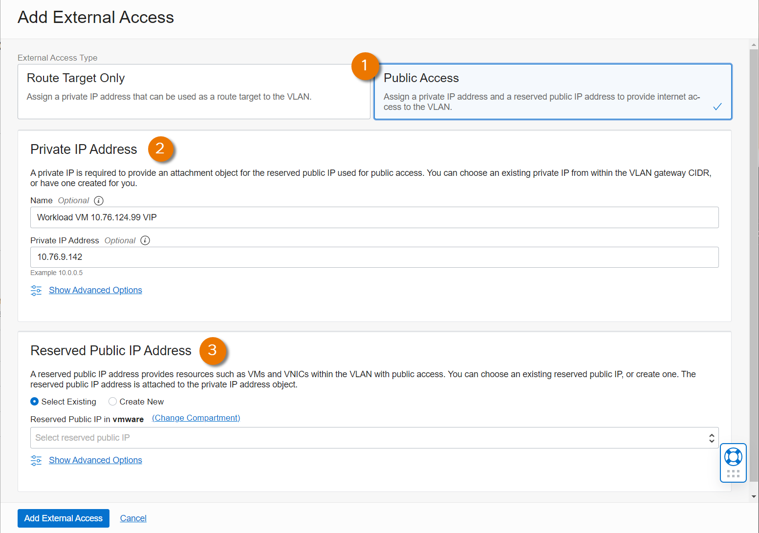
From the diagram we can see the main areas of the form, which are:
- We can use “Route Target Only” if we just need internal “on-net” access, but for our specific use case, we’ll select the “Public Access” option. Without selecting this, the bottom, “Public Address” section is hidden. This will give us a place to assign the Public IP address which the Internet Gateway will need from us.
- In the “Private IP Address” field we’ve entered a name, in this case showing the workload VM’s real IP address, but that’s just to help operationally. We could enter anything we wanted in that field. Below it is the IP address from the Uplink VLAN’s subnet which we selected for this VM.
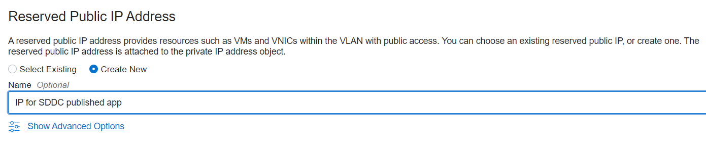
- Here we see a drop-down where we can pick an existing OCI Public Address we already have assigned to us but not currently in use. Or, selecting the “Create New” radio button we would be prompted to enter a name for the new Public Address which OCI would allocate for us, like this.
Submitting this (with that second blue button) takes us back to the VLAN details page where we can see our new External Access IP, and its newly assigned Public IP Address in the list!
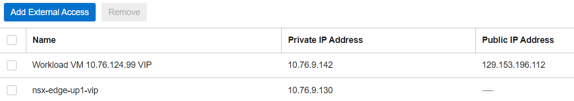
We said we needed three IP addresses to make this work, and they were:
- The actual address of our workload VM on the SDDC Logical Segment -
10.76.124.99. - The "intermediate" address on the Uplink VLAN's IP Subnet (and its OCID) -
10.76.9.142. - The Public IP Address -
129.153.196.112.
So, we have all the bits. Let's see if we can connect them all together. As it's always easiest to make things work in a diagram, let's start there.

Here we have a client on the Internet over on the right, connecting to a service on the workload VM over on the left. (1) to (6) are the same as the last time we used this image, but the generic “IP” label has been replaced with our dot-142 address. Although our “list of necessary addresses” started from our VM, the incoming flow works through them in the opposite order. Let’s examine the flow in more detail.
- The client, usually through DNS of course, targets our public address
129.153.196.112as its Destination. We won’t know the Source address unless this service is only available to selected clients, so we’ll just call the source “Any Allowed”. - After receiving the packet, the Internet Gateway works its magic and decodes that public destination as one belonging to our Uplink VLAN External Access IP/OCID. It delivers the packet to the VLAN having first NATed the Destination to our intermediate VLAN address
10.76.9.142. The client’s Source address remains unchanged, so we can return traffic to it. - As the packet hits the T0, the gateway needs to NAT the Destination of the packet to the “real” address of the workload VM -
10.76.124.99. Once again leaving the original Source address in place. - With the VM’s Destination IP address in place, NSX can route the packet over the T1 to the VM.
Configuring NSX NAT Rules
In order to connect things together we're going to need to add some more NAT rules in the NSX-T Manager.
Destination NAT for incoming connections
In (9) we said that the T0 had to match packets destined for our 10.76.9.142 from the Internet (the "Any" source) and change the Destination address (DNAT) to the internal, 10.76.124.99 address of our VM. That seems to be all the important bits for the NSX rule. In table form it looks like this:
| Name | Action | Source | Destination | Translated |
| DNAT Workload VM | DNAT | Any | 10.76.9.142 | 10.76.124.99 |
And in the NSX GUI it looks like this:
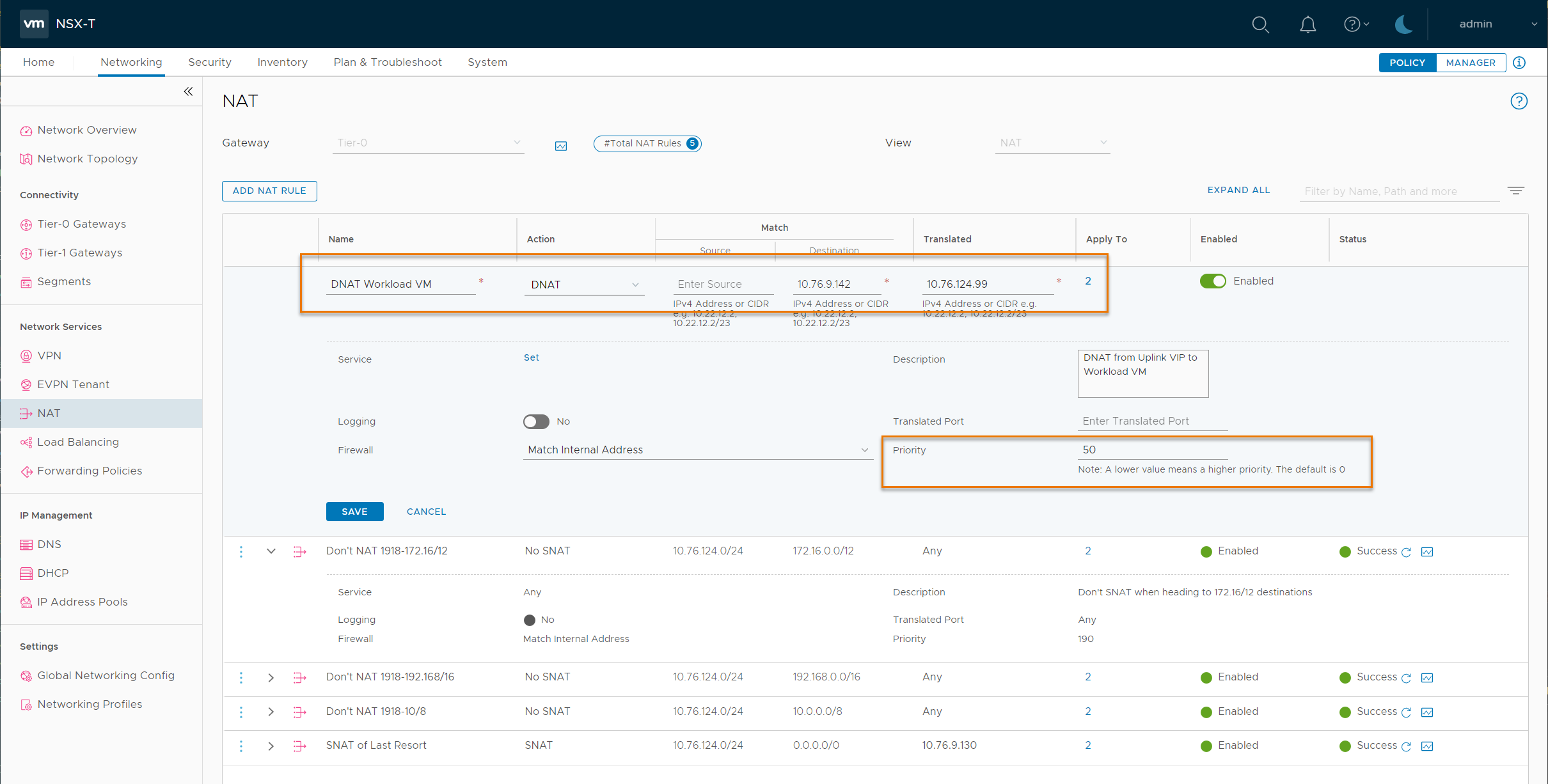
In the top highlighted area, we can see the details from our new rule. The "Name" should be some text to help future-us work out what on earth we did. We can't type "Any" into the UI but leaving the Source field empty does the same thing. The Matched "Destination" and "Translated" addresses just need typing carefully. This rule has been applied to "2" interfaces, the Uplink interfaces from the T0 to the Uplink VLAN. As they are currently our only external interfaces, leaving this field empty would achieve the same result. But, if we configure additional interfaces, having these rules only assigned where we want them might save future-us the pain of having to go back and assign Apply-To configs to all the existing rules.
In the lower highlight we can see the "Priority" field. In the last post we discussed priorities at length. Here, we just need to ensure the priority of this rule sits in the right place. Those four existing rules need to be at the end, so keeping our new rule "above" them is all we need to do in this simple example. The top No_SNAT rule is open so we can see its Priority. In this case, anything less than 190 will do for us. In a more complex Production environment, the order/priority of NATs can be really important, so we would work through the existing rules to establish where this one should go.
Source NAT for outgoing connections
As our T0 is running Active/Standby, when our workload VM replies to a connection from the Internet, that reply will go through the same T0 as the initial connection. This allows our Stateful DNAT rule to handle the Source NATing of our replies. Or, put another way, we don't need to explicitly NAT our workload VM to the Uplink VLAN's 10.76.9.142 address when we're replying to connections from the Internet as, in our scenario, NSX-T handles that for us automatically.
If our workload VM were to make a new connection out to the Internet, that connection wouldn't match any of the NAT rules except the last, "SNAT of Last Resort" one. That means, it would get lumped in with all the other SDDC VMs, using the model we described in the last post. That might be what we want, but we may, actually, want to have our workload VM hit the Internet wearing the same, elegantly tailored, Public IP address (129.153.196.112) as we're using for Incoming connections. If that's the case, we're going to need another NAT rule to make sure our VM gets SNAT'ed to that. Let's add it to the table...
| Name | Action | Source | Destination | Translated |
| DNAT Workload VM | DNAT | Any | 10.76.9.142 | 10.76.124.99 |
| SNAT Workload VM | SNAT | 10.76.124.99 | Any | 10.76.9.142 |
Remember, at this point we only need to SNAT to the Intermediate address on the Uplink VLAN. OCI will take care of swapping in our special public address as we hit the Internet Gateway.
Looking carefully, we see the priority of our new DNAT rule didn't actually matter. As the DNAT rule was designed with Internet traffic in mind, even if we had put it right at the end, after the SNAT of Last Resort (SoLR), things would still have worked, mostly as planned at least. Traffic hitting the T0's Uplink interfaces with a public Source address, destined (thanks to the Internet Gateway) for our VLAN External Access IP, would not have matched any of the original rules, so we would have gotten away with sloppy NATing.
But, if we also need a new SNAT rule so our Workload VM can use its "own" Public IP address, the position of that SNAT rule does matter. We need the specific "SNAT me to my personal Uplink VLAN address" rule to be matched before we hit the "SNAT of Last Resort" (SoLR). The neat-freak Architect in us demands the two NAT rules for this VM are next to each other, so we better give them both the same priority, and make sure it's low enough that they sit before, and so are matched before, those last four rules. We don't need to prioritize either one over the other, so having the same priority for both is fine.
A loose end or two
We're almost there (I'm sure you'll be relieved to read), just a couple of loose ends. In the flow diagrams we mentioned Security Lists and, for the Uplink VLAN, Network Security Groups. We won't dwell on specifics in this post, but we should ensure our firewall policies in the Security Lists, Network Security Groups and NSX-T configs allow the traffic we are trying to establish through all this. Okay, now back to our regularly scheduled loose-ends…
Fixing the Route Table
First, although in the packet flow diagrams, we hinted that the Route Table is now used to return traffic via the Internet Gateway instead of the original NAT Gateway, we didn't explicitly fix that. The default route in question is in the Route Table attached to the Uplink VLAN. To fix this, we can either change the target of the Route Table's 0.0.0.0/0 route target to the Internet Gateway, or we can replace the Route Table with a new/different Table whose default route correctly points to the Internet Gateway.
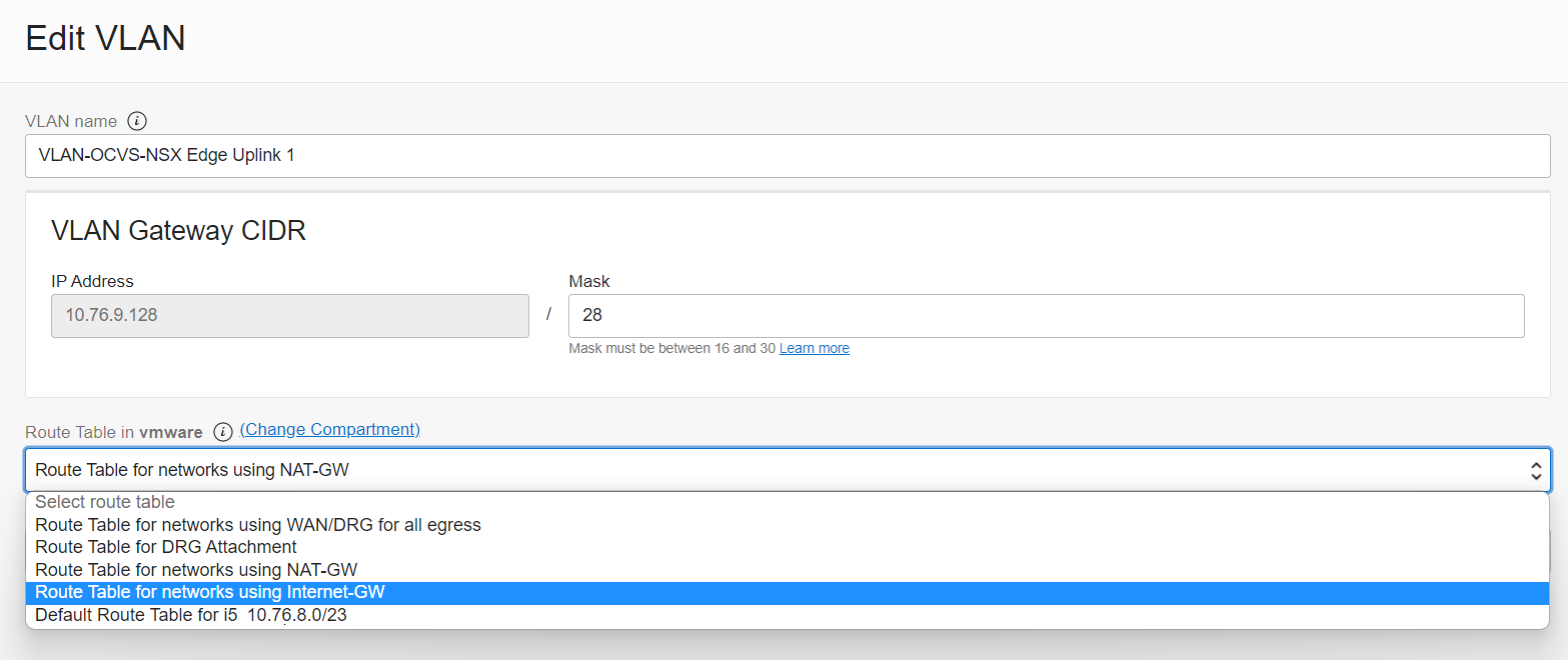
Here we can see the Route Table selection for the Uplink VLAN. In this environment we have a small number of Route Tables differentiated by the destination of their default routes. This makes it easy to switch from the "Route Table for networks using the NAT-GW" to the "Route Table for networks using the Internet-GW". It also makes it easy to select the appropriate Route Table for new networks without necessarily needing to create a new table for each new Subnet or VLAN.
Cleaning up our NATs
At the moment, our Internet "Any" Source match on the new DNAT rule is working well. Almost too well in fact. If we try and connect to that Uplink VLAN VIP 10.76.9.142 from within the VCN, or anywhere in our routable on-net environment, we'll go through the DNAT process too, as our RFC1918 source address will still be matched by the rule's "Any" Source. This may be absolutely fine; we might not care in which case we can get on with our day.
But, if we want to force on-net traffic to route directly, we'd have to either block those connections in the VLAN's Network Security Group rules, or insert a No_DNAT rule (or possibly multiple rules) before our new rules to prevent on-net sources from being accidentally NAT'd too. This can often become an issue if we're writing firewall rules on the NSX Gateway or DFW and forget that the workload VM is reachable through two, different, "Destination" IP addresses. Again though, this might not be an issue and/or we just may not care.
One last thing to fix. We need to use the Internet Gateway when we need inbound connections to the VCN (and with it both native OCI and OCVS resources). In OCI we would typically host externally reachable resources on a Public Subnet with a Route Table whose default route is via an Internet Gateway, and local (non-reachable) resources on Private Subnets, whose default routes to the Internet use a NAT Gateway for simplicity.
In the SDDC, we only have the T0 Gateway and its Uplink VLAN for all our ingress/egress traffic. The VLAN's Route Table can only have one default 0.0.0.0/0` route. When it pointed to the NAT gateway, with our four NAT rules in place, all the workload VMs could use the NAT Gateway’s public address and reach the Internet. Now that we need the Uplink VLAN to point to the Internet through an Internet Gateway, our one new workload VM is happy. But, in doing that, we broke Internet access for all the other VMs which don’t have their own public address(es). What we need to do now, is have the Internet Gateway behave like a NAT Gateway for all the “other” VMs which don’t have their own Public IPs. Fortunately, fixing this is not difficult.
Making the Internet Gateway behave like a NAT Gateway
Those VMs which don’t have their own Public IP/SNAT rules will fall through to our “SNAT of Last Resort rule. We used that to give them an OCID when they were using the NAT Gateway’s public address in the first post. Now, we’re using the Internet Gateway, we need to link that OCID to a public address as well, which currently we do not have. Fortunately, we can fix that quite easily. The OCID and Private IP address we used for the NAT Gateway came from the VLAN’s External Access IP. If we look at that on the OCI console (using the “…” icon on the right-hand end of the list item and choosing “edit”) we see that it’s currently a private Route Target only.
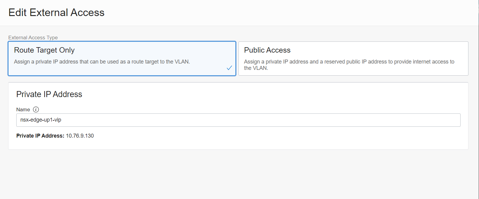
If we switch it to Public Access, we’re prompted for either selecting an existing Public IP (as shown), or, if we select “Create New”, attaching a name to a public address we’re about to request.

Hitting the Save button (which was unhelpfully clipped off the bottom of these screenshots) will complete attaching a Public address to the T0 VIP. This means when our workload VMs hit that SoLR rule and get Source NAT’d to the T0’s VIP, they will also inherit the new Public IP, and will be allowed to use the Internet Gateway.
We might decide that we want to use the existing VIP solely for routed traffic, and assign another for Internet NAT’ing, perhaps to aid future-us with troubleshooting. If that’s the case, we would just assign another IP on that VLAN, create a new Public Access VIP with that Private address and a new Public address, and change the SoLR to use the new VIP’s Private address as its “Translated” IP and we’re done.
To summarize
To summarize or, if you were impatient and jumped here for the short version, here it is.
Preparing the SDDC/VCN:
- Provision an Internet Gateway if you don’t already have one in your VCN.
- If the Uplink-1 VLAN’s OCI Route Table has a default route which points to a NAT Gateway, change the default route target to point to your Internet Gateway, or change the VLAN’s Route Table to one which already does.
- Add a Public IP address to the T0’s VIP on the Uplink-1 VLAN’s External Access list to allow “NAT Gateway-like” access for the general workload VMs.
To add a public address to a specific SDDC workload VM:
- Allocate a spare address from the Uplink-1 VLAN’s assigned subnet.
- Create a new “Public Access” External Access IP on the Uplink-1 VLAN using the new Private IP address above.
- Create a new DNAT Rule on the NSX-T T0 Gateway to NAT the Private IP address above to the Logical Segment IP address of the target VM.
- If the target VM should also use its dedicated Public IP for outgoing connections, create a SNAT rule to translate the target VMs Logical Segment IP address to that of its External Access IP.
- Make sure all the NAT rules are in the correct priority order.
- Amend any Security List, Network Security Group or NSX-T Firewall rules we need to actually permit the traffic we want to use our new service…
And you should be good to go.
Conclusion
Over the last twenty-five minutes or so, we recapped on outbound Internet Access for SDDC workload VMs using the OCI NAT Gateway. We introduced the OCI Internet Gateway and saw how it enabled native OCI workloads to be reached from the Internet and how, with a little work, we could adapt that model to allow SDDC workload VMs to be reachable from the Internet through their own Public IP addresses.
We saw that in doing that last bit we broke the carefully crafted general outbound Internet Access we worked so hard to build last time, and how to fix that before anyone noticed what we’d done. We saw where and how we needed to assign addresses to help our target workload VM become an Internet sensation, and, sigh, we added even more NAT rules to make this all hang together.
Closing comments
Once again, I’d like to thank my good friend Jason McKenzie for his help with this post. The improved readability of some key sections are thanks to Jason’s feedback whereas the mistakes and typos, as always, are mine… If you want to grab a copy of Jason’s awesome Getting Started with OCVS Ebook, head over to this post here on the VMware Cloud Blog!
This post was originally published on NotThe.Blog and is reproduced with permission. You can read the unabridged original here.
If you have any questions about the content of this post, or about Oracle Cloud VMware Solution, please drop them in the comments below.
Discover more from VMware Cloud Foundation (VCF) Blog
Subscribe to get the latest posts sent to your email.


