
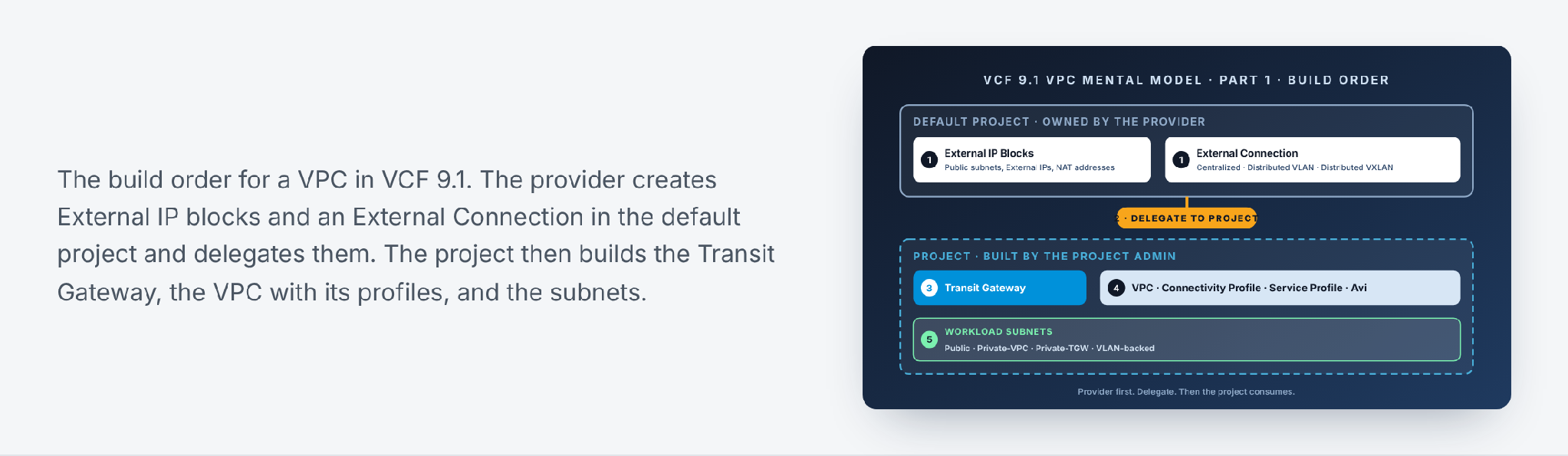
This is Part 1 of the series The VCF 9.1 VPC Networking Mental Model. It covers the order in which a Virtual Private Cloud (VPC) is built, from the provider’s External Connection down to the workload subnets. Later parts go deeper into each object.
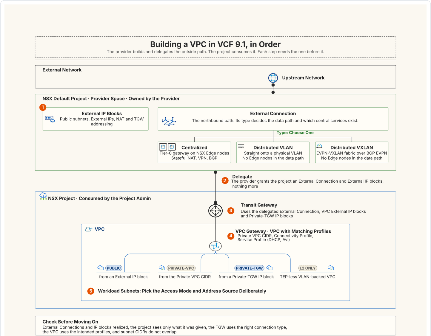
VPC networking in VMware Cloud Foundation (VCF) 9.1 is easiest to understand as a controlled hand-off. The default project holds the provider-owned constructs: External IP blocks and External Connections. A project is granted access to the ones it needs. Inside that project, a Transit Gateway sets the northbound model, a VPC consumes the matching connectivity and service profiles, and subnets become the networks the workloads sit on.
 Core idea
Build the provider-side connectivity first. Delegate it to the project. Then let the project consume the correct transit, connectivity, and service profiles.
In everyday terms, think of a large apartment building. The provider is the building manager. They own the street entrance (the External Connection) and decide which flat numbers exist (the IP blocks). Each project is a tenant who rents a floor and arranges the flats on it (the VPCs) as they like. Tenants never build a new door to the street. They use the entrance the manager gave them.
 1. Start in the default project
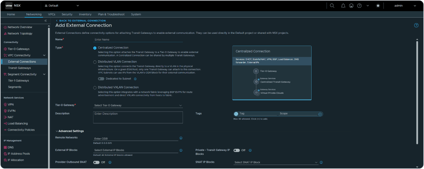
The default project is where the provider builds reusable external connectivity. Create the External IP Blocks needed for public subnets, External IPs, and NAT-translated addresses. Then define the External Connection that describes how the VPC domain reaches the physical network.
 Choose the External Connection type
The External Connection is not just a label. Its type decides the data path and which centralized services are possible.
- A Centralized Connection links the Transit Gateway through a Tier-0 gateway on NSX Edge nodes. The design guide lists stateful services for this model: Default Outbound NAT, custom NAT, Gateway Firewall, External IPs, load balancing, and VPN.
- A Distributed VLAN Connection gives lightweight connectivity to the data centre fabric with no NSX Edge nodes and no dynamic routing. Stateful services run on Virtual Network Appliances (VNAs). The design guide also describes a VLAN Backed VPC model, introduced in 9.1.1, for TEP-less designs. Part 4 covers it.
- A Distributed VXLAN Connection integrates with a standards-based EVPN-VXLAN fabric. The design guide lists it for 9.1.1. It needs EVPN Route Controller nodes to exchange BGP EVPN routes, and VNAs for stateful services.

 2. Delegate provider constructs to the project
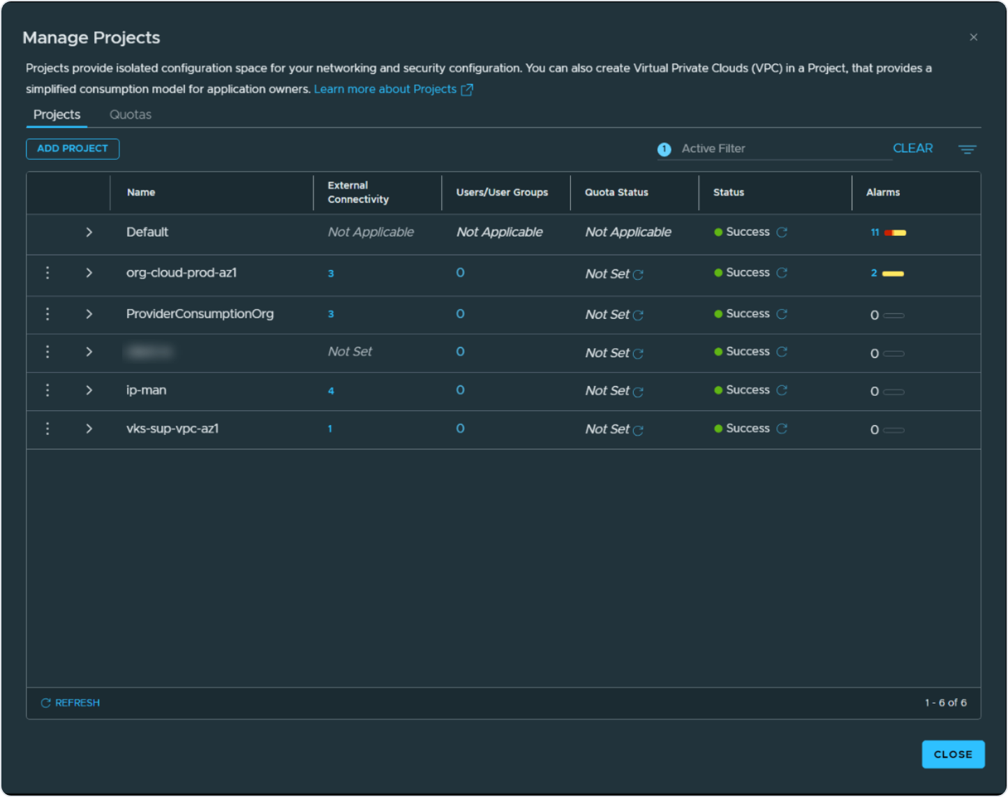
Projects give administrative and configuration isolation. Before a project administrator can build a VPC, the provider must grant the project access to the right External Connection and External IP Blocks. This delegation is the control point. It stops a project from consuming arbitrary provider networks or address space.
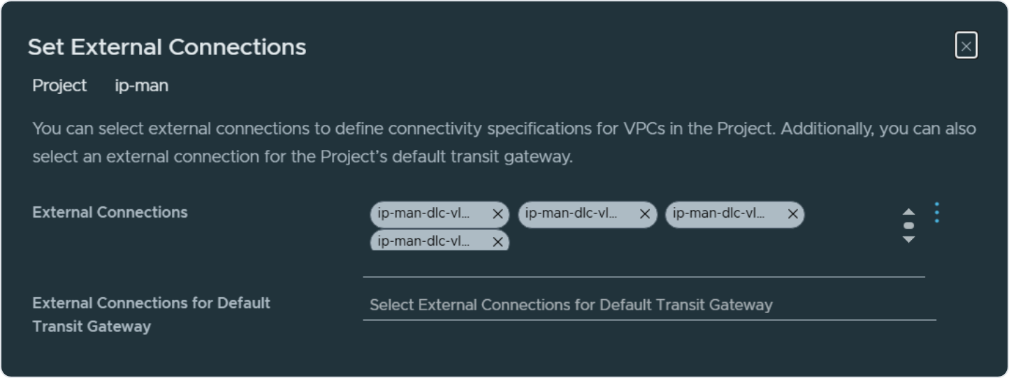
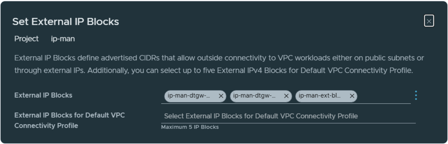
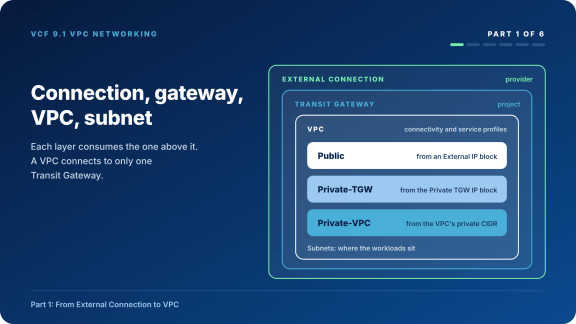
Architecture check. A Transit Gateway can have several External Connections, but they must all be the same type: all centralized or all distributed. A VPC connects to only one Transit Gateway.
 3. Create the project Transit Gateway
Move into the target project. Create the Transit Gateway from Networking, VPC Connectivity, Transit Gateways. Select the External Connection shared in the previous step. The Transit Gateway provides both inter-VPC communication and the connection to the outside network.
- Select the delegated External Connection.
- Enter the VPC External IP Blocks the gateway design needs.
- Add Private Transit Gateway IP Blocks when private transit addressing is part of the model.
- Confirm the connection type and the network span before attaching VPCs.
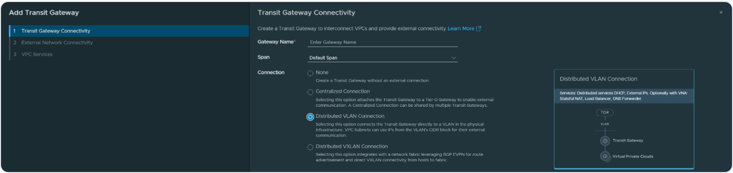
The project now has a defined path to the external network and the addressing it needs for VPC connectivity. Check that everything shows as realized before you go on.
 4. Create the VPC with the matching profiles
In the target project, open the VPCs tab and click Add VPC. Enter the private VPC CIDRs, select the VPC Connectivity Profile, and check the External and Private TGW IP blocks it brings. The profile is the reusable northbound configuration the VPC consumes.

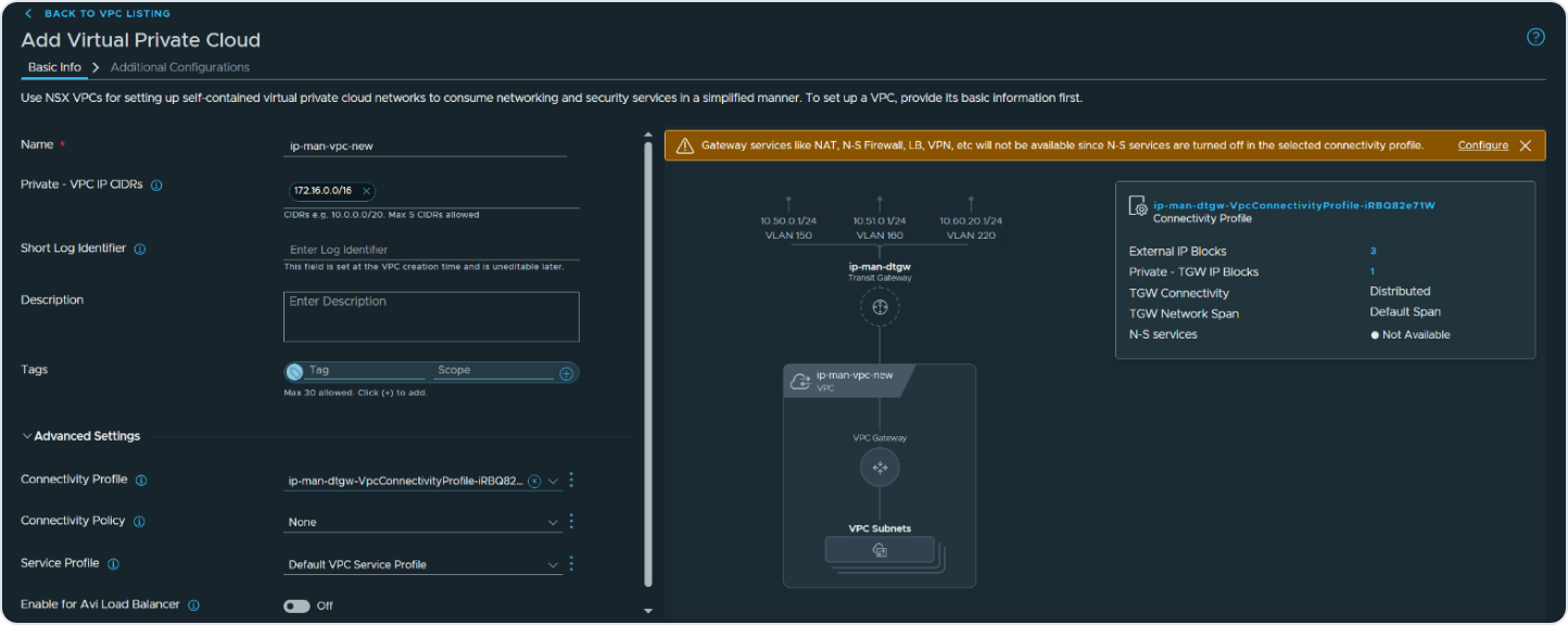
 Service profile and Avi integration
A VPC Service Profile holds the DHCP server or relay settings and the subnet profiles. Avi is a separate setting on the VPC. Turn on Enable for Avi Load Balancer so the Avi Load Balancer Controller can discover the VPC. The toggle has two conditions: at least one private IP block and at least one edge cluster assigned to the VPC. The private block is needed because the virtual service IP sits on a private subnet. The edge cluster lets the Service Engines get addresses from the DHCP server.
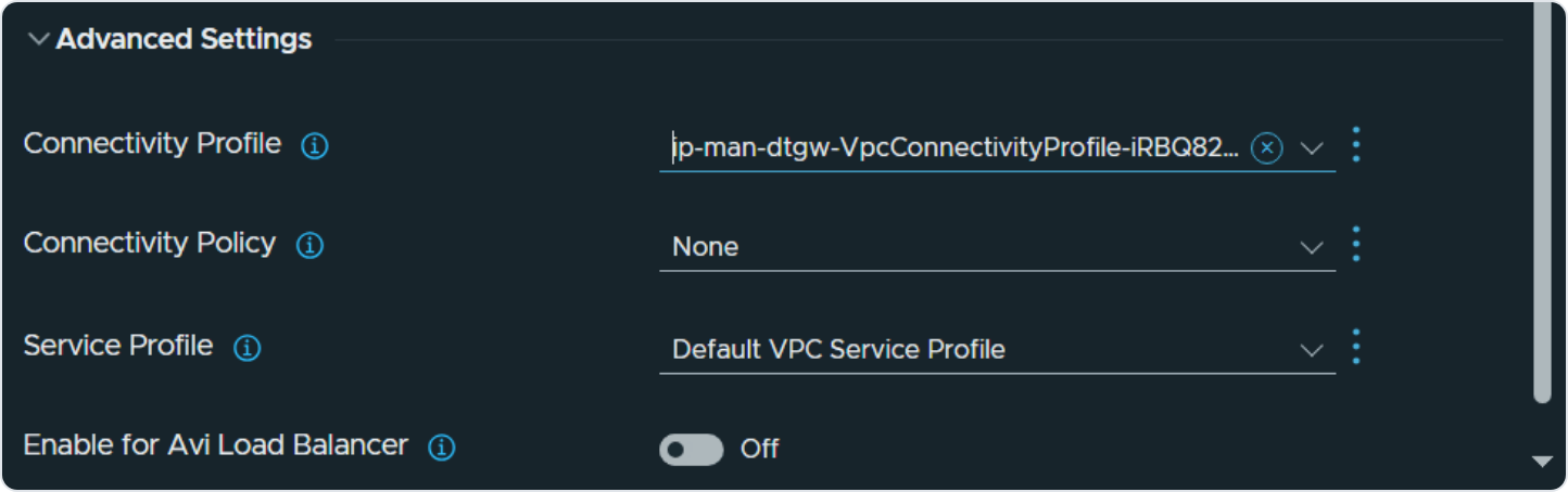
 5. Create workload-facing VPC subnets
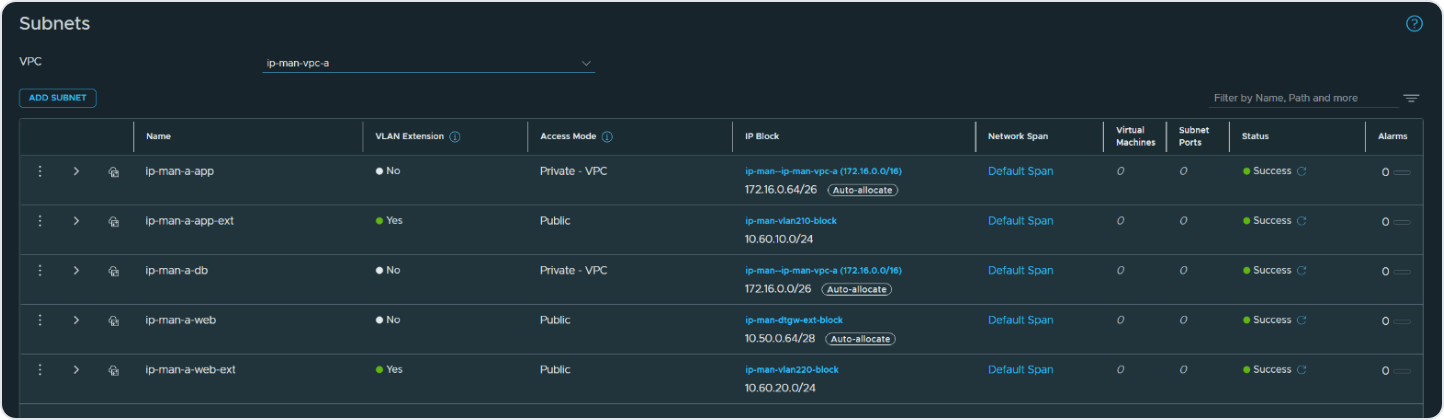
Create subnets only after the VPC has the right northbound and service context. Choose the access mode and the address source on purpose. Public subnets take addresses from an External IP block. Private-TGW subnets take them from the Private TGW IP block. Private-VPC subnets take them from the VPC’s private CIDR. VLAN extension uses a Distributed VLAN Connection and is covered in Part 4.


 Validation checklist
- All External Connections and External IP Blocks show successful realization.
- The project sees only the provider constructs meant for it.
- The Transit Gateway uses the correct connection type and External Connection.
- The VPC consumes the intended connectivity and service profiles.
- External IP blocks do not overlap within the project or on the same Tier-0 gateway. Subnets match their Public, Private or VLAN intent.
- Routes are present in NSX and in the physical network where advertisement is needed.
- NAT, firewall and external reachability behave as designed.
- VPCs with Enable for Avi Load Balancer on have a private IP block and an edge cluster assigned.
 Design takeaways
 Official references
- External Connections
- Transit Gateways
- Add a VPC Connectivity Profile
- Add a VPC Service Profile
- Configure VLAN-backed VPC Subnets in VCF 9.1
- Add an External Connection for Distributed VXLAN Connectivity
 What’s next
Part 2 takes each object from this build order and explains what it does: the IP blocks and why there are several, what an External Connection defines, how the Transit Gateway and the Connectivity Profile fit, the three subnet access modes, and where NAT comes in.
 About the co-author
This series is co-written with Abhilash Pillai, an Architect in Broadcom’s VCF Division. Over the past 16 years he has designed and delivered network, security, data centre, and cloud platforms. He holds the CCDE, CCIE Routing and Switching, CCIE Security, CISSP, CCSK, TOGAF and multiple VCF VCAP certifications.
Discover more from VMware Cloud Foundation (VCF) Blog
Subscribe to get the latest posts sent to your email.