The data center landscape has radically evolved over the last decade thanks to virtualization.
Before Network Virtualization Overlay (NVO), data centers were limited to 4096 broadcast domains which could be problematic for large data centers to support a multi-tenancy architecture.
Virtual Extensible LAN (VXLAN) has emerged as one of the most popular network virtualization overlay technologies and has been created to address the scalability issue outlined above.
When VXLAN is used without MP-BGP, it uses a flood and learns behavior to map end-host location and identity. The VXLAN tunneling protocol encapsulates a frame into an IP packet (with a UDP header) and therefore can leverage Equal Cost Multi-Path (ECMP) on the underlay fabric to distribute the traffic between VXLAN Tunneling Endpoints (VTEP).
Multi-Protocol BGP (MP-BGP) Ethernet VPN (EVPN) allows prefixes and mac addresses to be advertised in a data center fabric as it eliminates the flood and learns the behavior of the VXLAN protocol while VXLAN is still being used as an encapsulation mechanism to differentiate the traffic between the tenants or broadcast domains.
A Multi-Tenancy infrastructure allows multiple tenants to share the same computing and networking resources within a data center. As the physical infrastructure is shared, the physical footprint for these architectures is greatly reduced and consequently lowering the total cost of ownership since dedicated hardware is unnecessary.
From a pure networking standpoint, the use of different Virtual and Routing Forwarding (VRF) instances is critical to isolate the control plane and data plane for the different tenants.
VMware is the leader in the data center virtualization industry, both from a server and network point of view. The network virtualization capabilities of NSX-T have been enhanced with the support of MP-BGP EVPN and VXLAN.
This blog series will focus on NSX-T and EVPN in the data center. This first blog is an introduction to the technology and summarizes the 2 main EVPN features supported by NSX-T.
VRF Lite
It is important to understand the use case of VRF-lite to fathom the EVPN architecture and implementation within NSX-T.
A Virtual and Routing Forwarding instance is a method that consists of creating multiple logical routing tables within a single physical routing appliance as demonstrated in the following figure.
In a networking VRF topology, interfaces or sub-interfaces must be configured to participate in a specific tenant VRF.
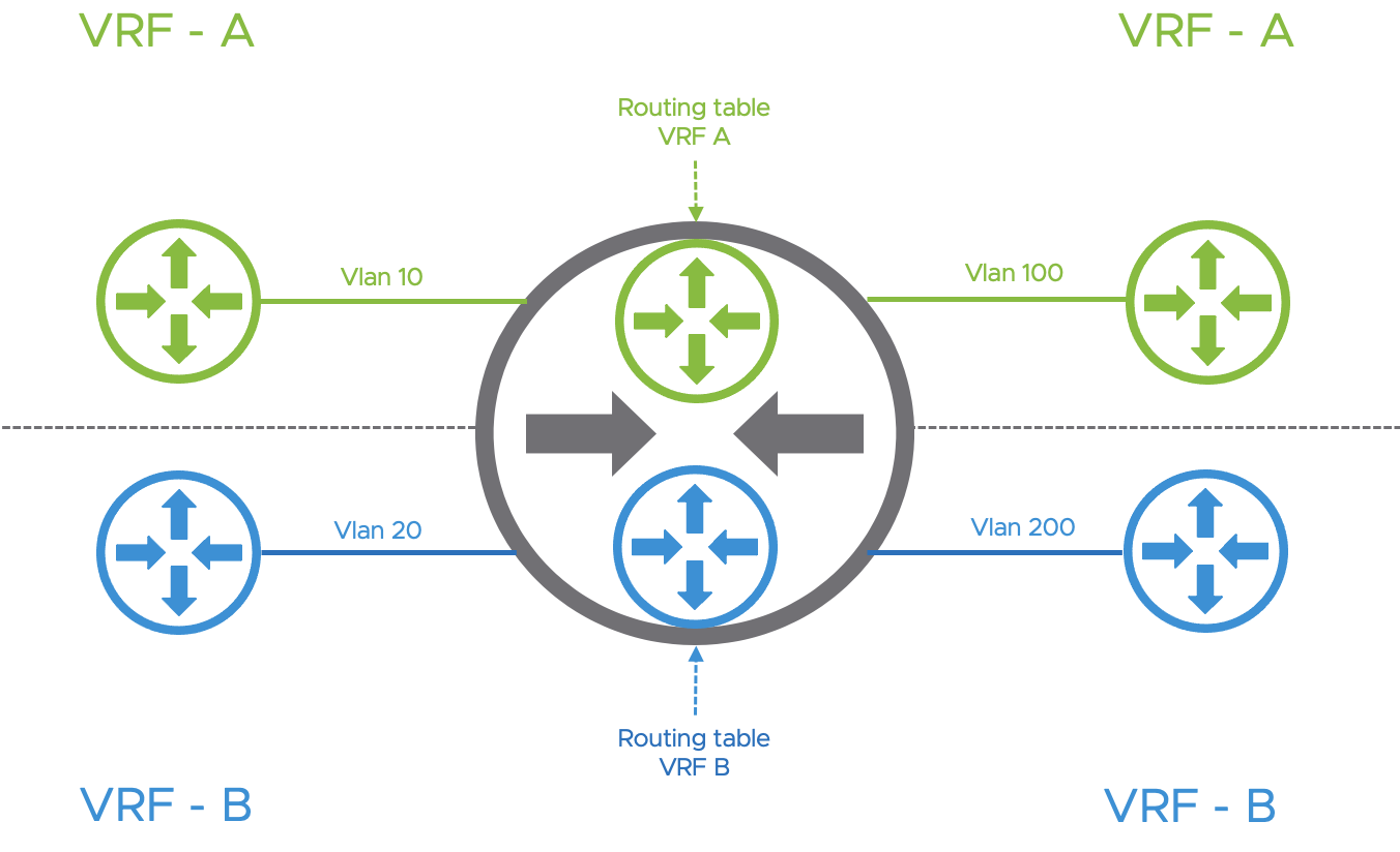
Each Virtual Routing and Forwarding Instances (VRF) are dedicated per tenant and provide control plane isolation. Therefore, an overlapping IP addressing scheme can be achieved between the tenants. From a data plane point of view, data plane traffic is differentiated using 802.1q VLAN Identifiers as demonstrated in the following diagram.
All the networking constructs for each VRF will have to be configured both on the Tier-0 and on the physical network fabric. The different network objects needed for a VRF lite architecture within NSX-T are the following:
- External interfaces per VRF and per Edge Node
- VLANs and Segments for each External Uplink Interface
- IP Addresses (v4/v6) for each External Uplink Interface
- BGP configuration, authentication, and BFD
The support of VRF-Lite in NSX-T allows the VRF instances to be extended from the physical network into the NSX-T domain and as close as possible to the compute workloads.
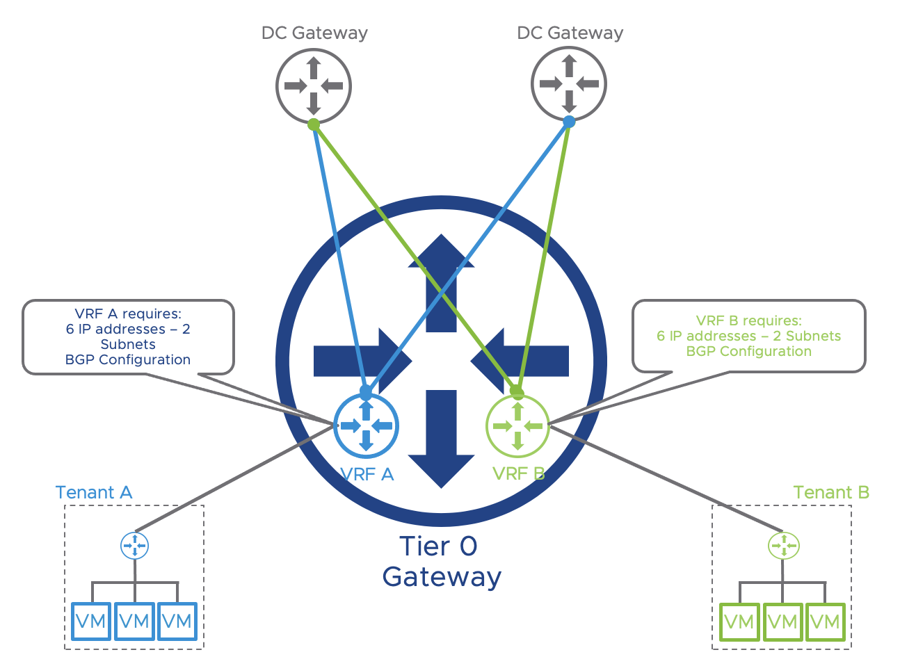
A single Tier-0 logical router can scale up to 100 VRF. Networking objects such as IP addresses, VLANs, BGP configuration, and so on, must be configured for each VRF which can cause some scalability challenges when the number of tenants is quite significant. Maintaining many BGP peering adjacencies between the NSX-T Tier-0 and the Top of Rack switches (ToR) / Data Center Gateways will increase the infrastructure operational load.
The following figure represents a logical NSX-T VRF lite topology where the NSX-T uplinks have different subnets (/31) shared on multiple edge nodes. In this topology, each VRF will consume 6 IP addresses, 2 subnets (configured on two edge nodes and DC Gateways).
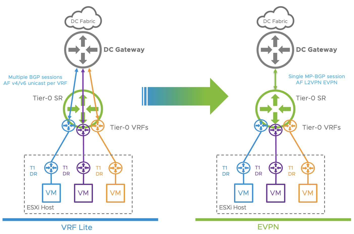
With EVPN, NSX-T overcomes the previously stated operational challenges by advertising the VRF prefixes over a single MP-BGP session between the DC Gateways and the Tier-0 parent gateway. The following figure demonstrates the difference between 2 multi-tenancy topologies using either VRF-Lite or MP-BGP EVPN. In the EVPN topology, a single MP-BGP peering adjacency between the NSX-T Tier-0 and the DC Gateway is enough to advertise all tenant’s prefixes.
NSX-T supports the following 2 EVPN Modes:
- EVPN Inline mode
- EVPN Route Server mode
EVPN Inline mode.
EVPN NLRI has been introduced in the BGP L2VPN/EVPN AFI SAFI and uses multiple route types to advertise IP prefixes and MAC Addresses.
When using MP-BGP, all VRF prefixes are advertised by the parent Tier-0 (Global Routing Table) to the DC Gateways using EVPN Route Type 5 over a single BGP session.
This overcomes the operational challenge introduced by a large number of VRF instances when using a native VRF lite architecture.
The following diagram represents an EVPN topology between the DC Gateways and the NSX-T domain.
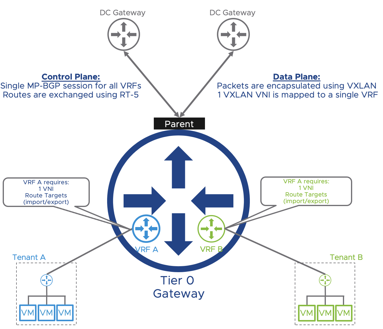
Control plane: As stated previously, it is handled by MP-BGP, and VRF prefixes are advertised as route type 5 (EVPN RT-5) with a VNI mapped to a particular VRF and an extended community that specifies the VXLAN encapsulation. Route distinguishers allow the prefix to be unique. Route targets allow the Data Center Gateway and NSX-T to import/export the IPv4 and IPv6 Network Layer Reachability Information in the right tenant VRF instance. The following figure represents how VRF prefixes are exchanged using EVPN Route Type 5 between the Tier-0 and the DC Gateway. The VNI and Route Targets are in this case unique per VRF. Route distinguishers, Route target, and VNI must be designed and configured on both the NSX-T Tier-0 and Data Center Gateways.
On VRF-A the Route Target will be imported and exported with a value of 65000:100. The VNI associated with VRF-A is 200100.

Data plane: Geneve is the encapsulation protocol used for traffic that flows within the NSX-T domain (between hypervisors and edge nodes). In addition to the TEP Interface for Geneve traffic (and BFD), VXLAN is the tunneling encapsulation protocol used when the Tier-0 needs to send traffic to the Data Center Gateways (North-South Traffic). The VXLAN TEP is different than the Geneve TEP and is usually loopback interfaces redistributed into BGP in a traditional Clos fabric. Each tenant VRF will be assigned a VXLAN Network Identifier (VNI) to differentiate the network traffic for each VRF between the DC Gateways and the NSX-T Tier-0.
The following figure describes the different headers used in a VXLAN encapsulated frame.

The following figure represents the VXLAN traffic encapsulation for the different VRFs in an NSX-T EVPN in-line topology.

NSX-T EVPN In-line mode allows a data center to scale by an order of magnitude as creating a new tenant does not require an additional BGP peering. Doing so greatly reduces the time it takes to deploy a new tenant. Network Traffic is totally isolated between tenants in the NSX-T domain and the number of network constructs consumed (IP addresses, VLANs, Interfaces, BGP processes) is reduced.
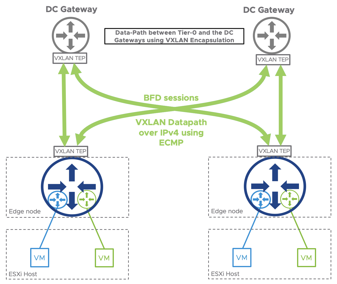
NSX-T EVPN In-line mode leverages ECMP to send the traffic to multiple DC Gateways as depicted in the following figure.
Finally, NSX-T using EVPN inline mode offers a true multi-tenant solution for your data center.
EVPN Route Server Mode
EVPN Route Server mode is supported since NSX-T 3.2 and enhances VMware NSX-T Networking Virtualization Overlay capabilities.
By using EVPN Route Server mode, Service providers can build out a 5G network that provides network slicing from mobile edge to core. It enables agile operations with scale and maximum performance.
This feature is service provider-centric as it allows NSX-T to process a very large amount of north-south traffic since the Datapath bypasses the edge nodes and encapsulates the network traffic using VXLAN between the hypervisors and the DC Gateways.
Using the EVPN Route Server mode, the edge node is not in the datapath but is still playing a key role by advertising the EVPN prefixes and VXLAN Tunnels endpoints to the DC gateways.
EVPN Route Server mode requires the use of a Virtual Network Function (VNF).
As its name implies, a VNF virtualizes network features such as vBNG and will advertise the VRF prefixes to the Tier-0 gateway.
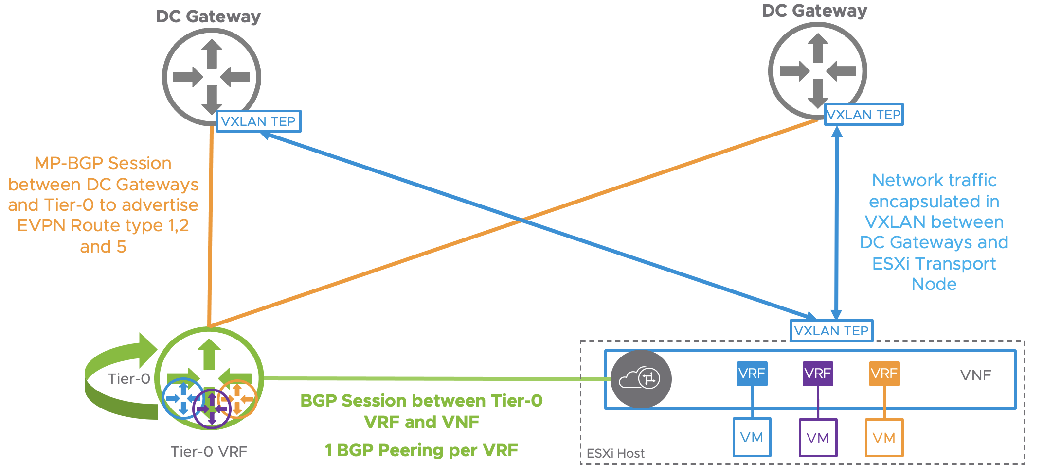
The following figure represents the following:
- Control plane used for EVPN route server mode:
- Between the VNF and the Tier-0 VRF (Green).
- Between the Tier-0 and the DC Gateways (Orange)
- Data plane:
- Between the DC Gateways and the Hypervisors using their VXLAN TEP interfaces.
Identical to EVPN in-line mode, we are going to provide more details on both the control plane and data plane for this use case:
Control plane:
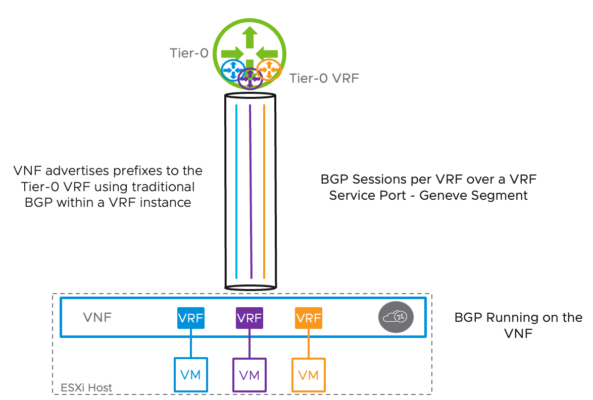
BGP between the VNF and the Tier-0 VRF: The following figure represents a VNF hosted on an ESXi hypervisor. The VNF will host the different VRF instances and will establish an E-BGP peering adjacency with a Tier-0 VRF using IPv4 and IPv6 address families.
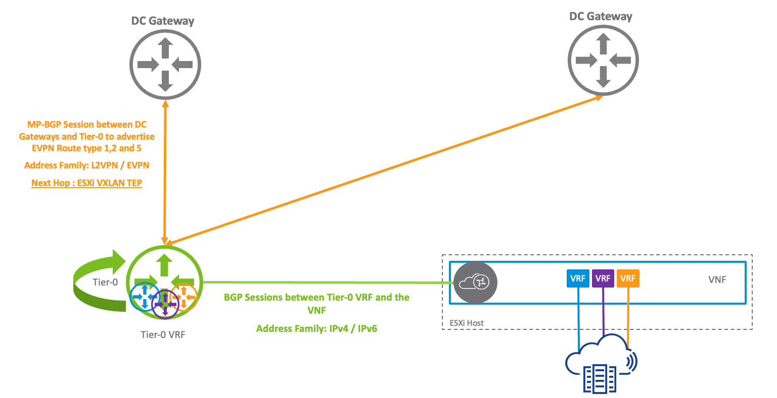
BGP between the parent Tier-0 and the Tier-0 VRF: The following figure depicts the BGP adjacency between the parent Tier-0 and the DC gateways. L2VPN EVPN AFI/SAFI are enabled on this BGP peering. Prefixes are advertised using EVPN Route types 1,2 and 5.
Data plane:
In EVPN Route Server mode, the ESXi TEP can encapsulate the traffic using either Geneve (East-West traffic) or VXLAN (North-South) enhancing the networking virtualization feature of the VMware ESXi hypervisor.
To send the network traffic northbound, the traffic is encapsulated using VXLAN and sent directly to the DC gateway TEP as demonstrated in the following diagram. The traffic is sourced by the ESXi TEP interface that is already created on the transport node during NSX-T installation.
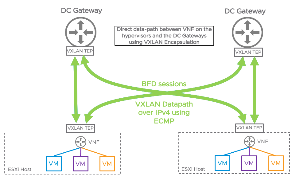
BFD sessions are established between the TEP interface on the ESXi hypervisors and the DC Gateways to detect failures and reduce the convergence time in the fabric.
EVPN Multihoming is also supported, the ESXi TEP interfaces will create multiple VXLAN tunnels to the DC gateways. Doing so will increase the number of available datapath links and provide redundant connectivity to the physical network fabric.
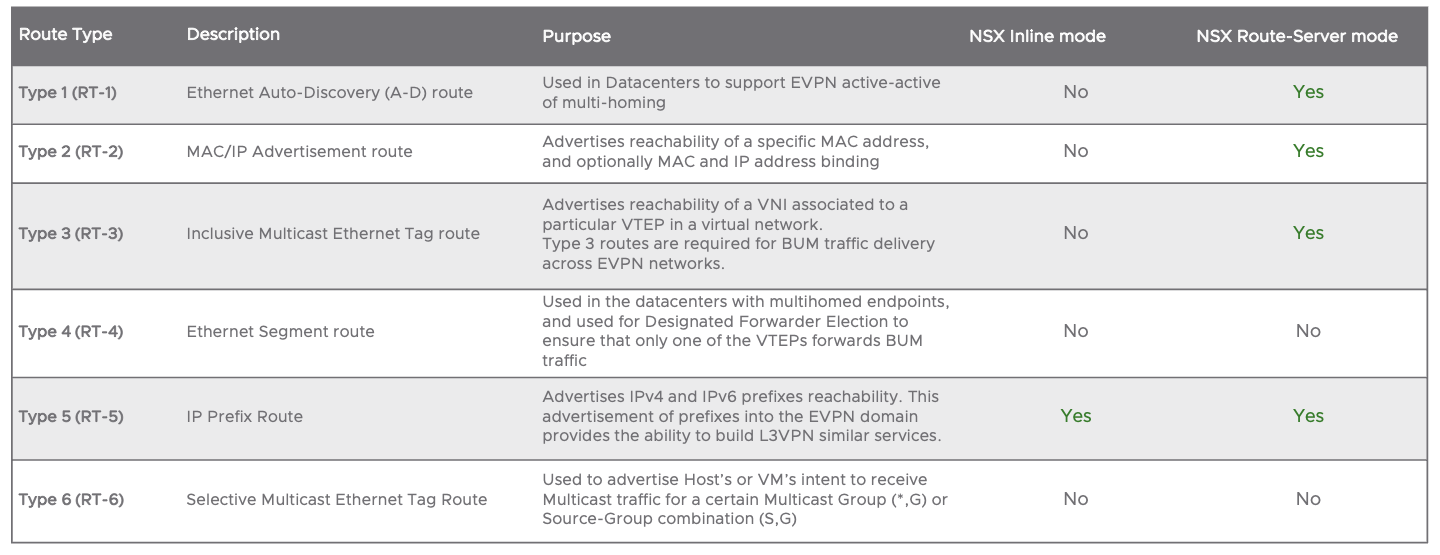
As stated previously, NSX-T EVPN Route-Server mode is a service provider-centric feature that allows the north-south network traffic to be exchanged directly between the hypervisors and the DC gateways using VXLAN encapsulation bypassing the edge-node. For that reason, it improves the throughput processed between the hypervisors and the DC gateways. As of NSX-T 3.2, the use of a VNF is mandatory to exchange VRF prefixes to the Tier-0 instances. EVPN Route type 1,2 and 5 are supported for this implementation. The edge node is still necessary to advertise the prefixes using MP-BGP L2VPN/EVPN address family and subsequent address family.
In both Inline and Route-server mode, EVPN greatly extends the network capabilities of NSX-T and allows a new tenant to be provisioned without creating new BGP peering adjacencies in the fabric for each VRF.
The following table shows the different EVPN Route types supported by NSX-T:
NSX-T Next Steps:
To learn more about NSX-T, check out the following links:
NSX-T Data Center Product Page
NSX-T Data Center Design Guide
NSX-T Data Center Documentation
NSX-T Data Center Hands-on Labs (HOL)
Migrate to NSX-T Resource Page


Comments
0 Comments have been added so far