VMware NSX-T 3.2 is one of our largest releases — and it’s packed full of innovative features that address multi-cloud security, scale-out networking, and simplified operations. Check out the release blog for an overview of the new features introduced with this release.
Among those new features, let’s look at one of the highlights. With this release, Migration Coordinator now supports a groundbreaking feature addressing user-defined topology and enabling flexibility around supported topologies. In this blog post, we’ll look at the workflow for this new feature — starting with a high-level overview and then digging into the details of User Defined Topology. For more information on Migration Coordinator, check out the resource links at the end of this blog.
Migration Coordinator
Migration Coordinator is a tool that was introduced about 3 years ago with NSX-T 2.4. It enabled customers to migrate from NSX for vSphere to NSX-T Data Center. It’s a free and fully supported tool built into NSX-T Data Center. Migration Coordinator is flexible, with multiple options enabling multiple ways to migrate based on customer requirements.
Prior to NSX-T 3.2, Migration Coordinator offered two primary options:
- Migrate Everything: Migrate from edges to compute, to workloads in an automated fashion and with a workflow that resembles an in-place upgrade on existing hardware. This mode only needs enough resources to host NSX-T manager appliances and edges along with enough capacity per cluster to be able to vMotion all VMs from one host at a time in each cluster. However, this mode only supports certain fixed topologies.
- Distributed Firewall Only: In this mode, customers have the flexibility to custom design their NSX-T deployment and migrate only the security policy. This mode may be used to migrate to NSX-T on existing hardware in-place or to a green field deployment of NSX-T. However, as the mode name implies, this mode only allows migration of DFW configurations.
With the NSX-T 3.2 release, Migration Coordinator now allows:
- Flexibility in topology when migrating everything in-place and
- An option to migrate all configurations when migrating to a green field instance of NSX-T.
User Defined Topology
User Defined Topology mode delivers flexibility in terms of the topology used for migration. In this mode, users have the flexibility to create a topology in NSX-T and specify how the existing NSX for vSphere objects are mapped to the new NSX-T objects. For example, users can flexibly map the Edge on NSX for vSphere with the corresponding objects, such as a T0 on NSX-T. This mapping is used by the Migration Coordinator to migrate the configuration over from NSX for vSphere to NSX-T.
User Defined Topology Prerequisites
NSX for vSphere and vSphere itself need to be in a green state, with no unpublished firewall rules.
NSX for vSphere
- A topology that would map to NSX-T objects and design principles. Please check out the NSX-T Reference Design Guide [link] for more details.
NSX-T
- Migration Coordinator on NSX-T Manager Appliance needs to be enabled via ssh using the command “start service migration-coordinator”.
- Configure a topology that maps to the existing topology of NSX for vSphere.
Others
- Migration Coordinator on NSX-T Manager Appliance needs to be enabled via ssh using the command “start service migration-coordinator”.
User Defined Topology Workflow
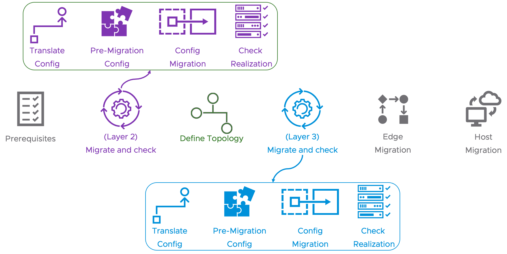
Migration Coordinator’s user defined topology mode, at a high level, consists of six simple steps that include a provision to map the objects from NSX for vSphere with NSX-T objects. Following are the high-level steps of user defined topology mode:
- Prerequisites
- Check whether prerequisites are met for migrating to NSX-T. This includes items such as versions used, etc. This step includes a one-time import and check of configuration from NSX for vSphere. On the migration coordinator GUI, this step is called “Import Configuration”.
- Migrate and check realization status of L2 elements.
- Define Topology
- This stage allows mapping the NSX for vSphere objects with NSX-T objects.
- Migrate and check realization status of L3 elements.
- Edge Migration
- Host Migration
The following image shows the 6 overall steps of the user defined topology migration mode:
Folks who are familiar with the migration coordinator workflow, in general, will recognize the Prerequisites, Edge Migration and Host Migration steps. The three new steps help with (1) separating the config migration of L2 / L3 elements, and (2) providing an area to help define the topology — that is, mapping the NSX for vSphere objects with NSX-T objects.
Layer 2 and Layer 3 Config Migration Stages
The steps for Layer 2 and Layer 3 config migration are expanded to allow granular control over resolving configuration-level issues, config migration, and check realization stages. The following image shows the full view, including the individual steps that are specific to Layer 2 and Layer 3 config migration stages:

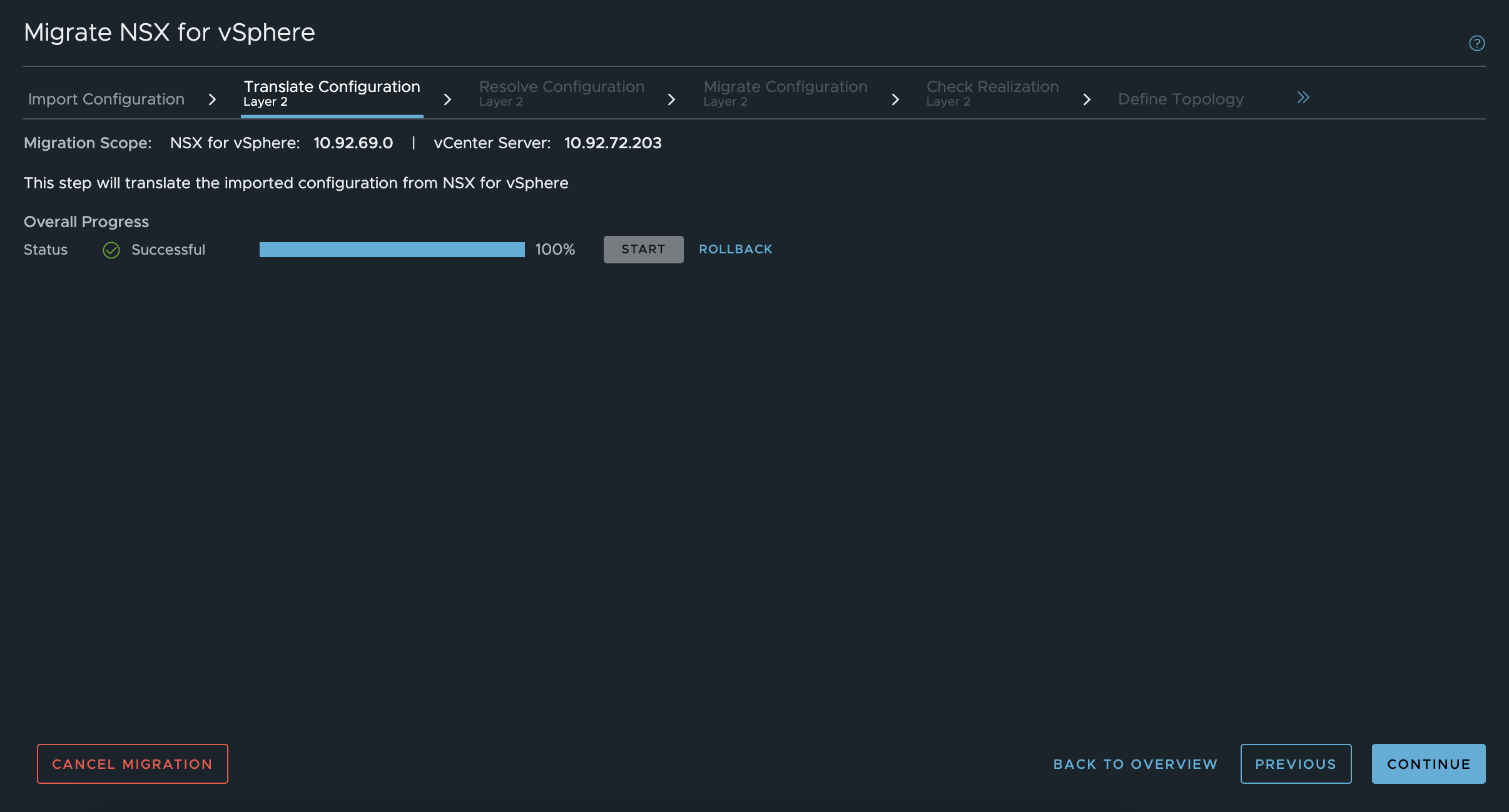
The Translate Config, Config Migration, and Check Realization steps in both the L2 and L3 config migration stages are very simple, with very little user interaction other than to click the button to start the process.
For example, the following image shows the Translate Config step of L2 Config Migration.

Resolve Configuration
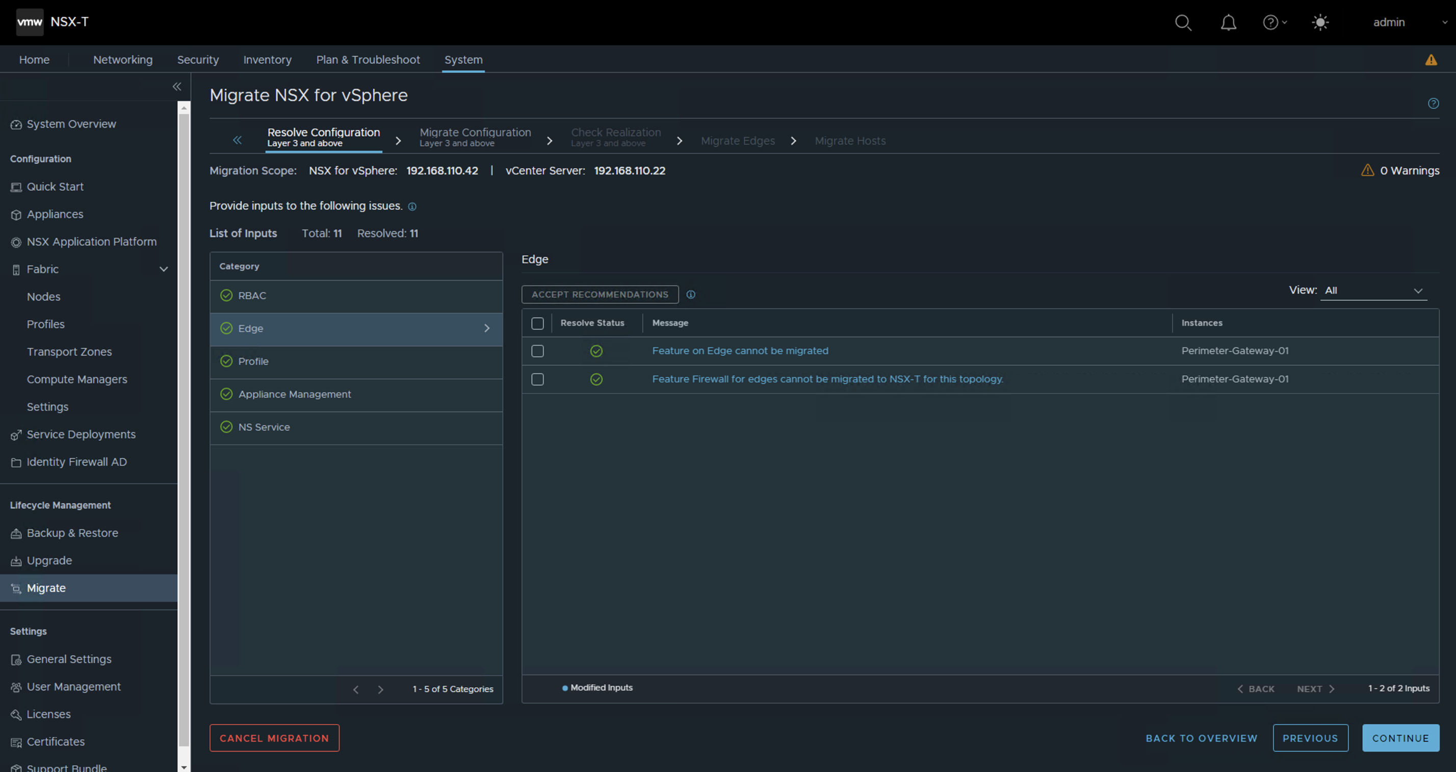
Both the L2 and L3 config migration stages have a pre-migration config stage, called Resolve Configuration, that allows the user to either confirm the recommended changes or give feedback, based on requirements. For example, in the following image, Resolve Configuration of L3 config migration stage informs us that one of the features is not supported for migration.

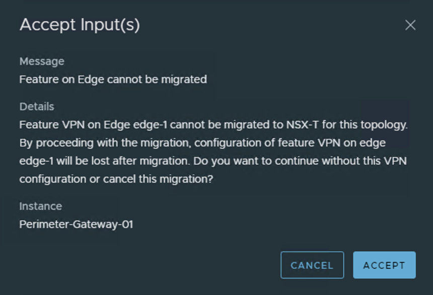
Clicking on the line item shows details about the particular feature that is not supported and an option to either continue without the concerned feature or cancel the migration, as shown in the following image.

Define Topology
User Defined Topology mode adds a Define Topology section that allows mapping of NSX-v objects with NSX-T. There are multiple ways to map. For smaller deployments, selecting the right objects via GUI may be the simplest approach. For larger deployments, Migration Coordinator also has a way to import the mapping via a json file.

Conclusion
With the release of NSX-T 3.2, Migration Coordinator adds a new mode, called User Defined Topology, in addition to the many existing modes that provide for multiple migration approaches, from in-place migration of everything to DFW only migrations. With the new User Defined Topology migration mode, customers have the flexibility to create the topology of their choice in NSX-T and migrate their existing NSX for vSphere to this new topology. With User Defined Topology mode, migrations to NSX-T from NSX for vSphere are no longer tied to the five topologies supported by in-place migration mode.
Resources
Want to learn more? Check out the latest documentation on Migration Coordinator.
To see what’s new in NSX-T 3.2, check out the announcement blog.


Comments
0 Comments have been added so far