When it comes to migration from one infrastructure to another, there are always complexities and risks involved. Finding the most appropriate approach is key to successful delivery of desired outcomes, but depends on the customisations that exist in the current environment and other operational, technical and business features. The technical solution, presented in this post is just a single step in the entire process of migrating workloads from a NSX-V-based environment to a NSX-T-based, which is also enabled with NSX projects.
The overall migration strategy in this use case is “Lift-and-Shift” between two separate environments. The purpose of this post is to outline the steps necessary to perform in order to create Layer 2 bridges between NSX-V and NSX-T environments and potentially do workload migration between the two environments. The products involved are as follows:
| Product | Version |
| VMware vCenter Server® (Target) | 8 update 1 |
| VMware vCenter Server® (Source) | 7.0.3.01100 |
| VMware NSX® (Target) | 4.1.0.2.0.21761691 |
| VMware NSXV (Source) | 6.4.14.20609341 |
| VMware ESXi™ (Target) | 8 update 1 |
The purpose of this post is to guide you on how to set up a starting environment with NSX-V and a destination environment with NSX-T, enabled with NSX projects, and how to create the Layer 2 bridging between the two in order to enable vMotion between the two environments. The actual workload migration is not the focus of the article, but rather the underlying NSX setup. In production environments, the source (NSX-V) will be created and its topology and overall setup might differ from the one described in the article.
NSX-V setup
The NSX-V environment will sometimes be referred as “source” environment. It consists of 2 ESXi hosts, both with NSX-V installed on them and managed by a single vCenter server. I have created a couple of VMs, each located on a separate ESXi host in order to first test the overlay of the NSX-V environment. Each VM is in a separate subnet, obtaining IP address via DHCP. There is only one transport zone.

Setting up the NSX-V environment
Prerequisites
- NSX-V Manager
- vCenter server with at least one ESXi host
Prepare the hosts for NSX-V
Login to vCenter. Go to “Networking and Security”
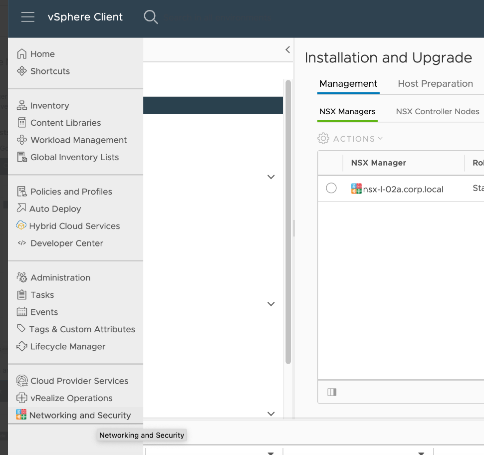
Go to “Installation and Upgrade” > Host preparation. In this menu, you need to install the NSX packages to the target ESXi cluster. Upon successful installation, you should see all checkboxes in green as in the screenshot below:

Create ID range for segments
Go to “Logical network settings”. Then click “Edit” for the “Segment IDs”. Enter a range for the IDs:

If you are dealing with a prepared/production NSX-V environment this would be fulfilled. Just check whether such a pool exists.
Create the NSX-V transport zone
Then move to the next tab – “Transport zone” to create the actual transport zone (TZ). Click the “ADD” button. Select the replication mode to “Unicast” and select the ESXi cluster that was installed with NSX-V in step 2:
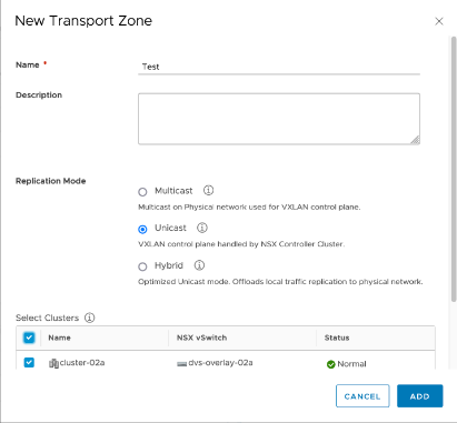
If you are dealing with a prepared/production NSX-V environment, such TZ would exist and you do not need to create it.
Create the logical switches
Navigate to the “Logical switches” menu and click “ADD” button. You only need to specify the name of the switch and select the TZ to which it will be associated.

In reality, we need by one logical switch (LSW) for the data subnets, one transport LSW for connectivity between the DLR and the ESG and another LSW for connectivity between the DLR and the DHCP ESG.
If you have a production/prepared NSX-V environment, all the LSWs would exist and you do not need to create them.
Create the DLR and the ESGs
The setup of the lab consists of 1 DLR, 1 ESG for north-south traffic and another ESG dedicated for the DHCP services only. The network topology looks like this:
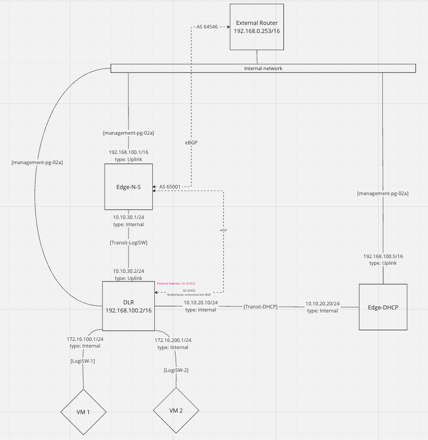
All three objects (DLR and two ESGs) are essentially VMs that will be running on the vCenter. Their vNICs will be connected to the respective logical switches, created in the previous step. Their management vNICs will be connected directly to the management port group, which presents them to the “Internal network” (192.168.0.0/16)
During creation, make sure you enable the SSH access for troubleshooting purposes:
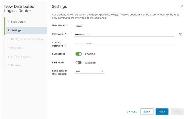
Also, you need to create the control VM. For it, you need to select where to be deployed, where the management interface will be connected to and what is going to be its IP address:

NOTE: The above process is repeated as many times as the ESGs and DLRs exist. In our lab, this number is 3.
Then you need to create the interfaces of the DLR and the ESGs. Depending on your topology, you create different amount and type of interfaces. For our lab, the DLR has the following interfaces:
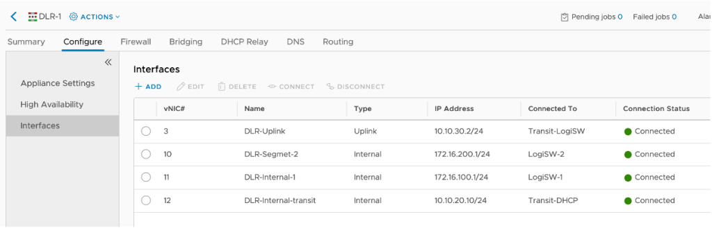
The DLR has two subnets attached to it – 172.16.100.0/24 and 172.16.200.0/24, each one connected to its dedicated LSW, an Uplink interface for connectivity to the north-south ESG and another internal interface for connection to the DHCP ESG.
The north-south ESG has the following interfaces:

The ESG N-S uplink is an interface, connected to the “Internal network” over which the ESG holds BGP adjacency with the “External router”
NOTE: The “Internal network” is used also for management subnet of all the VMs in this lab.
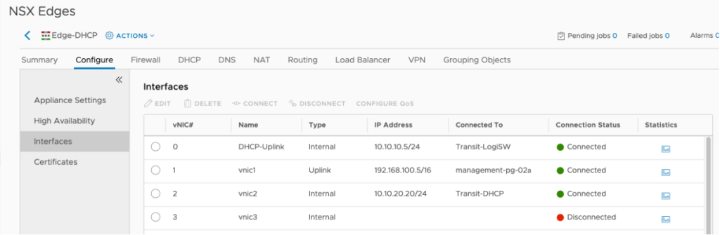
The DHCP ESG has the following interfaces:
Configure the NSX-V routing
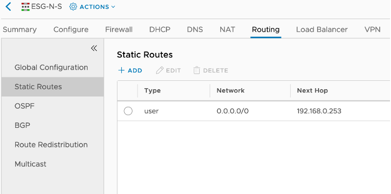
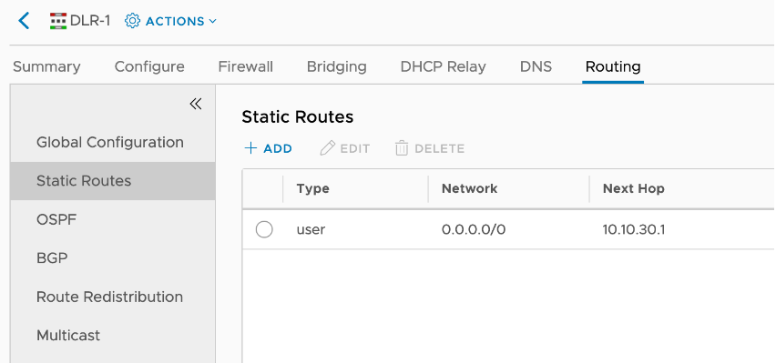
Due to the nature of the virtualised lab environment, the External router does not advertise a default route over BGP. Therefore, the ESG N-S must be configured with a static default route towards the External router, and the DLR must be configured with a static default route towards the ESG N-S:
In order for the DHCP to work, the DHCP ESG must be configured with static routes towards all subnets that are connected beehind the DLR in order to reach them:

On top of this, the ESG N-S must have BGP peering with the External router (northbound) and another with the DLR (southbound)


The DLR advertises the subnets that are attached to it via BGP, so that the ESG N-S can advertise them to the External router. This way the VMs within these subnets will have Internet connectivity:
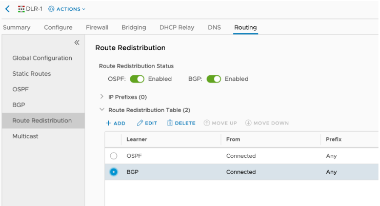
NOTE: Disregard the OSPF redistribution in the screenshot above.
Create DHCP relay on the DLR to point to the DHCP ESG
The IP addresses that the DLR uses to reach the DHCP ESG is the one via the [Transit-LSW] link – 10.10.20.20. In the “DHCP relay agent” section, we add the subnets that will be “DHCP enabled”

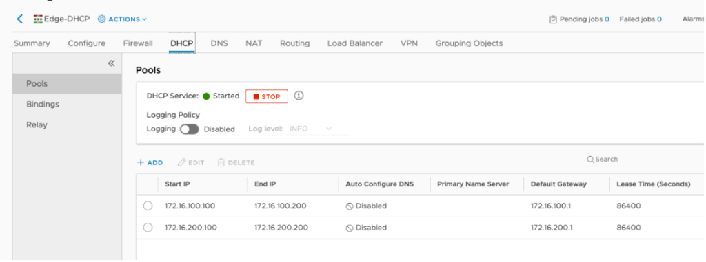
Configure DHCP server
On the DHCP ESG we need to create the pools for the two subnets that will be hosting VMs and enable the DHCP server functionality.

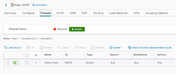
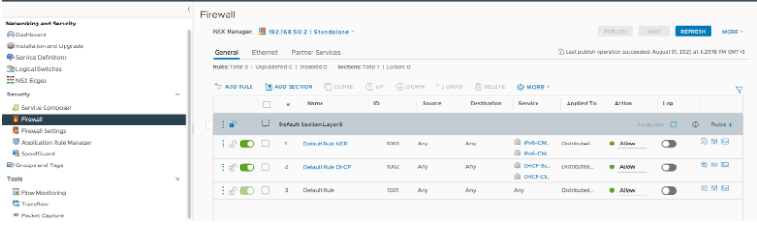
Stop the DFW everywhere in NSX-V
For the lab purposes, we do not need any FW inspections so it is safe to disable the ESG/DLR firewalls by turning all rules to action “Allow”
NOTE: In production environments, this is not recommended. You should only enable the traffic that will be used for the actual testing.
Stop firewall on the VMs
In order for the Ping to succeed between the two VMs, we must stop their build-in firewall as well. Since we are using Photon VMs, this can be achieved via the following commands:
#systemctl disable iptables.service
#systemctl stop iptables.service
The reason why each VM is on a different ESXi host is to be able to test the overlay – if the is a misconfiguration in it, the VMs won’t be able to reach each other.
NOTE: In production environments, this is not recommended. You should modify the VM firewalls to enable only the traffic that will be used for the actual testing.
NSX-T setup
Since we have verified NSX-V side fully operational, now we need to configure the NSX-T side. The goal here is to deploy the NSX-T edge node onto the NSXV-enabled vCenter, which node will be providing connectivity between the two environments. In this section, we will walk through the setup of the NSX-T environment, then enhance it with projects, create segments, and finally apply bridge profiles to them via API. The key thing is that once we reach the point of creating the NSX-T segments, they will be disconnected from their T1 gateway, thus all of their north-south traffic will be flowing over the bridge to the DLR in NSXV and via the ESG-N-S to the internet.
Also, the VMs onto these NSXT segments will obtain IP addresses via the DHCP ESG, located in the NSX-V environment. The topology is the following:

Add NSX-V vCenter as Compute manager in NSX-T
Go to System > Fabric > Compute Managers > Add Compute manager. You must use the administrator account for this task. The final result should be that NSX-T sees two compute managers – vc-l-01a (the initial NSX-T-enabled one) and vc-l-02a (the initial NSX-V-enabled one)


NOTE: “Cluster-02a” is not configured with NSX-T. This is the desired state. Only “cluster-01a” should be prepared with NSX-T. Remember – cluster-02a is the one prepared with NSX-V. We are adding it as a compute manager in NSX-T so that the NSX-T manager can deploy its VM that will be used for bridging.
Create Transport zone for bridging
System > Fabric > Transport Zones > Add Zone
Create a TZ that will be used especially for bridging purposes. The two interfaces (“Uplinks”) of the bridging edge node will be placed into this TZ. You need to specify the name of the policies, referred in the uplink profile that will be applied to the edge node, literally exactly (case sensitive).

NOTE: For the purpose of our lab, we will be bridging only two source LSWs, hence we need to create just two uplinks in the TZ for briding. If you intend to bridge for example 3 LSWs, then you would need to create 3 uplinks.
Create Uplink profile
System > Fabric > Profiles > Uplink profiles > Add profile
The purpose is to create a special uplink profile that will be applied to the Edge node for bridging. Do not add any LAGs, go directly to “Teamings”. You cannot delete the default one, just add two more and specify exactly the names that you placed in the TZ configuration:

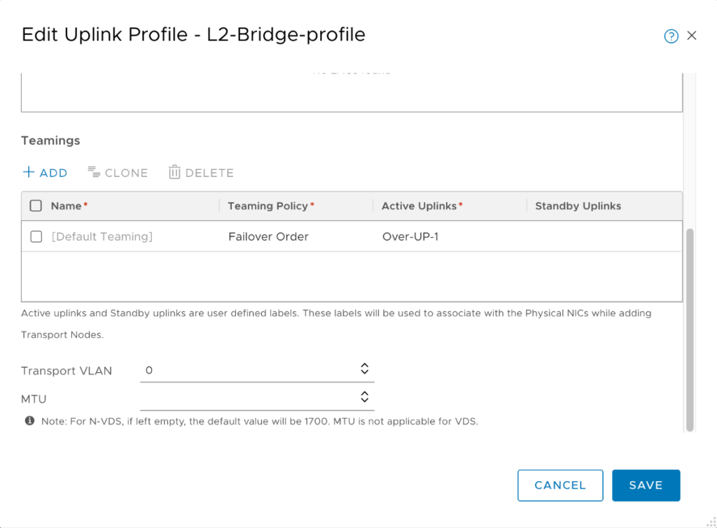
NOTE: For simplicity, in my lab environment I am using VLAN 0, but you should try to avoid VLAN 0 and use a different VLAN for production purposes.
However, we need to create another profile that will be used for all edge node “connections” to the NSX-T overlay TZ. We will use just a single interface for this purpose. This is because the bridging edge node will have two switches in it – one facing the NSX-V environment (with two interfaces, because we plan to bridge two segments simultaneously) and another one facing the NSX-T environment (with just a single interface).
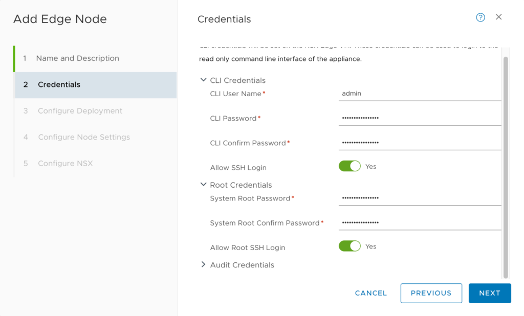
Create Edge node for bridging
System > Fabric > Nodes > Edge Transport nodes > Add Edge node
As explained, this is just another VM that will be deployed on NSX-V vCenter and has multiple connections, establishing the actual bridge. During its creation, do not forget to enable SSH access to it for troubleshooting purposes:

As explained, it will have two LSWs – SW1 will be connected to the NSX-T overlay TZ with a single interface, while SW2 will be part of the specially created Bridging TZ and will have two interfaces:

The workloads in NSX-T will be connected to the segments, associated with the overlay TZ. The resources in NSX-V are connected to the logical switches, associated with the overlay TZ that we created in the first chapter (“Test” TZ). The third transport zone involved in this setup is the bridging TZ, which is VLAN-based and we created it in the “Create transport zone for bridging” step.

As per the best industry practices, it is recommended to have two Edge nodes for HA, therefore you need to repeat the entire process from this step twice in order to create two VMs for the bridging. The end result is that you should see the two newly created nodes under System > Fabric > Nodes > Edge Transport nodes:

Add the bridging edge node to the edge cluster
System > Fabric > Nodes > Edge Clusters > Add edge cluster
An edge node cannot exist on its own. It must be part of a cluster. There is nothing special that we need to do in this cluster configuration, just assign the nodes to a cluster:

For the purpose of a lab environment, you can use just a single node, but for production environments, it is highly recommended to have two nodes for HA purposes.
(Optional) Test the NSX-T overlay
The testing methodology is exactly the same as in NSX-V – create a couple of VMs in NSX-T, place them on different ESXi hosts, which are enabled for NSX-T, and connect to the same segment (same TZ as well), disable the FW, and test reachability between them. The purpose is to verify that the NSX-T side of the lab environment is properly operating.
Create NSX-T Projects
More and more implementations these days relay in the native multi-tenancy feature of NSX-T – Projects. Once you create a project and start creating resources in it, if you navigate to the segment, belonging to a specific project, you will notice that in the settings section, there is no option to attach a profile for bridging. In this guid it is described how to perform this as well.
Navigate to the top-most ribbon of the screen, where it says “All projects” and select “Manage”

Click “Add Project” and select the T0 gateway of your choice (the only one available in our lab is the default T0 GW). In “Edge Cluster” field, specify the initial edge cluster that was created with the NSX-T installation – “edge-cluster-01a”, not the cluster we created for bridging.

Create NSX-T segments within the context of a project
Select “Project 1” > Networking > Segments > Add segment
Create the two segments to resemble the two logical switches in NSX-V, with the same subnets. Do NOT place DHCP profiles on those segments, as the NSX-V DHCP ESG will be providing this at this point. Also, disable “Gateway connectivity”. The reason is because we want to test if a VM on T side can reach a VM on V side and go out to the Internet over the V side.

Bridge the two environments
Up until this point we have two separate environments, working independently from each other. The steps from now on are related to creating the Layer 2 bridge between the two environments.
Configure the Logical switch to connect to the Edge Bridge
The purpose of this step is to configure virtual wire port group of the NSX-V LSW to enable connectivity with the NSX Edge bridge. There are two ways to achieve this:
- Enable Promiscuous mode and Forged Transmits
- Enable MAC learning and Forged Transmits
In our lab we will opt for the first method. All the steps for both methods are described in this guide – https://docs.vmware.com/en/VMware-NSX/4.1/migration/GUID-206CF244-3171-4146-9C60-43A797B15043.html
This step is necessary to be performed only on the logical switches that will be “extended” to the T environment.
vSphere > Inventory > Networking > (select the logical switch) > Actions > Edit Settings > Security

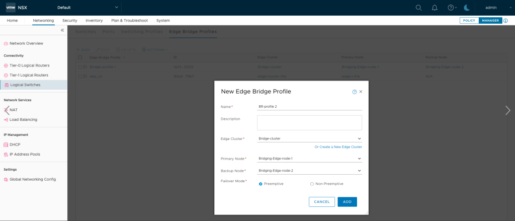
Create Edge bridge profile in NSX-T
Networking > Segments > Profiles > Edge bridge profile
You can perform this step from the “POLICY” mode or from the “MANAGER” mode of NSX-T. For thr purpose of our lab, it is done from the “POLICY” mode. This step ties the cluster we created for bridging purposes and the dedicated bridging edge node, deployed in NSX-V ESXi host.

Apply the Edge bridge profile to the NSX-T segments in projects
If you navigate and edit a segment, belonging to a NSX-T project you will notice that there is no option to set an Edge profile to it. The only way to do this is via API.

In order to apply the profile to the segment, you need to follow this guide – https://docs.vmware.com/en/VMware-NSX-T-Data-Center/3.2/migration/GUID-AC7335D9-C475-4003-A379-749968428955.html
Once applied, the VM in the T side will be able to obtain IP address from the DHCP ESG in the V side and also ping the VMs in the V side over the bridge.
Next steps
If you would like assistance in deploying the solution, please reach out to VMware Professional Services or your VMware sales executive.


Comments
0 Comments have been added so far