
When deploying VCF Automation, one of the most common points of confusion on the deployment parameter screen revolves around FQDN mappings, Virtual IP (VIP) behavior, and how load balancing operates under the hood. Here is a complete breakdown structure explaining the 3-node High Availability (HA) architecture, the native load balancing layer, and how external GSLB/load balancers fit into the design.
1. The 3-Node Architecture & The 5-IP Requirement
In a standard High Availability (HA) deployment, VCF Installer provisions 3 virtual machine appliances to form a Kubernetes-based container runtime cluster for VCF Automation.
A common question is: If it’s a 3-node deployment, why does the installer require a pool of 5 IP addresses?
- 3 Active Appliance Node IPs: Assumed in this example as 172.16.50.11, 172.16.50.12, and 172.16.50.13. These are assigned directly to the individual VMs for node-to-node communication and cluster management.
- 2 Reserved Expansion/Buffer IPs: IPs 172.16.50.14 and 172.16.50.15 stay in reserve within the subnet pool. They are consumed dynamically during non-disruptive rolling upgrades, node redeployments, and day-2 cluster scale-outs.
In addition to the 5 node pool IPs, 2 Fully Qualified Domain Names (FQDNs) for VIPs are required outside the IP pool. These two mandatory FQDNs – the VCF Automation FQDN for public user/API traffic and the VCF Automation Services Runtime FQDN for internal management control plane operations – must each map to dedicated static Virtual IP (VIP) addresses provisioned on the same management network.
Per-Node VIPs for External Load Balancing: When integrating an external load balancer (such as AVI) or utilizing round-robin DNS, the external balancer targets individual virtual IP endpoints assigned to each node (Node 1 VIP, Node 2 VIP, and Node 3 VIP). Since VIP 1 already covers Node 1, two additional per-node VIPs are required specifically for Node 2 and Node 3. Keeping all per-node VIPs within the same management subnet simplifies Layer 2/Layer 3 routing, avoids cross-subnet hair-pinning, and ensures seamlessly aligned health probes across the cluster.
2. Decoupling the Two FQDNs
The deployment form requires two distinct FQDN inputs. Both resolve to floating Virtual IP (VIP) addresses on the same management subnet, but they serve completely different purposes:
| FQDN Parameter | Sample Mapping | Who / What Uses It? | Primary Function |
|---|---|---|---|
| VCF Automation FQDN | vcfa01.rainpole.io→ 172.16.50.2 (VIP 1) | End Users, Cloud Admins, REST APIs | Public/user ingress for accessing the self-service portal, catalog UI, and provisioning APIs on port 443. |
| VCF Automation Services Runtime FQDN | vcfa01-sr01.rainpole.io→ 172.16.50.3 (VIP 2) | SDDC Manager, VCF Ops, Platform Services | Private, machine-to-machine control plane endpoint for lifecycle management, cluster upgrades, and node orchestration. |
Do the nodes have 2 NICs? No. Having two FQDNs is a logical ingress design, not a dual-NIC requirement. Both VIPs and all 3 active node VMs operate on a single virtual network interface (NIC 0) connected to the same VCF Management Network Port Group.
3. High Availability (HA) Cluster Architecture
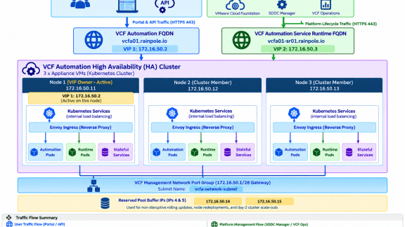
Without External Load Balancer :
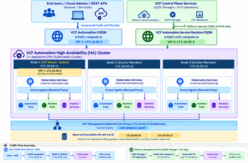
Detailed Breakdown of Traffic Paths and Operational Flow:
Direct End-User Ingress (Blue Flow): End users, cloud administrators, and external API callers establish connections directly to the primary VCF Automation FQDN (172.16.50.2) over HTTPS (port 443). This ingress pathway serves the user interface, catalog portal, and public consumption APIs without requiring any intervening third-party load-balancing appliances.
Direct Management Ingress (Green Flow): Management control plane components—specifically SDDC Manager and VCF Operations—route dedicated lifecycle, cluster orchestration, and node maintenance traffic directly to the separate VCF Automation Service Runtime FQDN (172.16.50.3). Isolating this machine-to-machine traffic ensures control plane operations remain uninterrupted by end-user requests.
Embedded Virtual Load Balancer Layer: The native Kube-vip, and Envoy ingress stack automatically hosts both Virtual IPs (VIPs) across the cluster. It monitors node health, handles transparent VIP failover if a node becomes unavailable, and evenly distributes incoming HTTP and API calls across the internal application pods running on Nodes 1, 2, and 3.
With External Load Balancer
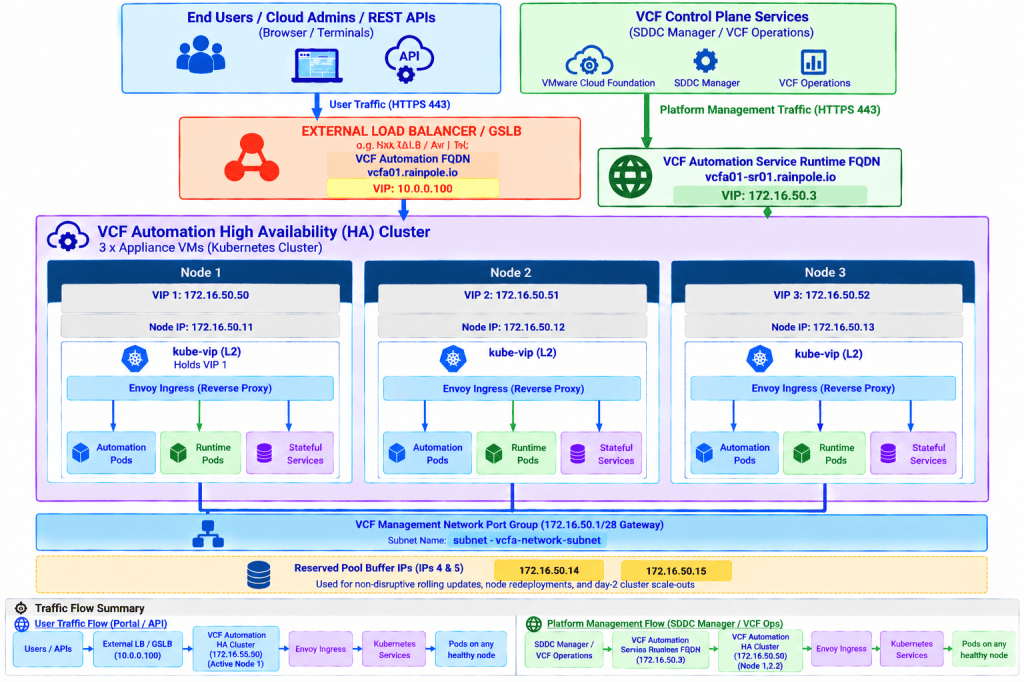
Detailed Breakdown of Traffic Paths and Operational Flow:
User Traffic Path (Blue Flow): Inbound external network requests initiated by End Users, Cloud Administrators, or REST API clients are routed to the enterprise-level External Load Balancer / Global Server Load Balancer (GSLB) at IP 10.0.0.100. This GSLB layer acts as the primary global ingress point, performing health checks, DNS routing, and SSL termination or proxying. The external load balancer forwards these incoming user requests to the primary tenant-facing virtual IP address, VIP 1 (172.16.50.50). From VIP 1, traffic enters the native Embedded Virtual Load Balancer Layer, which performs internal Layer 7 ingress routing across the three underlying application node instances.
Control Plane Path (Green Flow): Internal platform orchestration and management components—specifically SDDC Manager and VCF Operations—completely bypass the External Load Balancer and GSLB layer to avoid operational dependencies. They establish direct machine-to-machine management communication via VIP 2 (172.16.50.3). This isolated control plane path handles critical cluster maintenance, lifecycle management (LCM), automated upgrades, and platform telemetry, ensuring management stability regardless of external traffic state.
Cluster Integrity & High Availability: The native Embedded Virtual Load Balancer Layer (utilizing kube-vip, and Envoy proxies) remains active continuously across all 3 nodes. This embedded stack dynamically maintains ownership of VIP 1 and VIP 2, handles local pod-level ingress routing, and ensures automatic floating VIP failover between nodes in the event of an appliance failure.
4. Purpose of Native Load Balancer vs. External Load Balancer
The Native Load Balancer (Internal)
- What It Is: An embedded load-balancing stack (Kube-vip combined with Envoy proxies) deployed automatically inside the 3 appliance VMs during installation.
Purpose:
- Binds and hosts the two Virtual IPs (VIP 1 and VIP 2) across the 3 nodes.
- Handles local failover: if Node 1 goes down, another healthy node automatically claims the floating VIPs within seconds.
- Distributes incoming HTTP/API calls locally to application container pods running across all 3 VMs.
- Does It Go Away If You Use GSLB/External LB? No. The native load balancer remains 100% active. Even if external DNS/GSLB directs traffic to the local site, the native load balancer is still required to route requests into the local cluster nodes.
The External Load Balancer / GSLB (Global)
- What It Is: An external enterprise appliance (e.g., HA Proxy, Avi LB, F5 BIG-IP GTM) that operates at the global DNS layer.
Purpose:
- Evaluates health probes across multiple geographic data centers.
- Directs global user traffic to the active local site VIP during cross-site disaster recovery (DR) scenarios.
- Delegates the user-facing domain (vcfa01.rainpole.io) dynamically without touching site-local management interfaces.
5. When to Use Internal vs. External Load Balancing
| Scenario | What to Use | How It Is Implemented |
|---|---|---|
| Simple and Standard internal facing Deployment | Native Load Balancer Only | Zero external LB required. VCF handles VIP creation, kube-vip failover, and ingress routing automatically out of the box. |
| Local Single Node High Availability | Native Load Balancer Only | Handles single-node VM failures within the cluster seamlessly without external hardware. |
| Tenant-Facing External Security & Multi-Site | External GSLB | Positioned upstream from the 3-node VCF Automation cluster, GSLB actively monitors the primary VCF Automation VIP. It safeguards internal VCF Automation nodes by preventing direct exposure while securing all inbound external and tenant-generated traffic. |
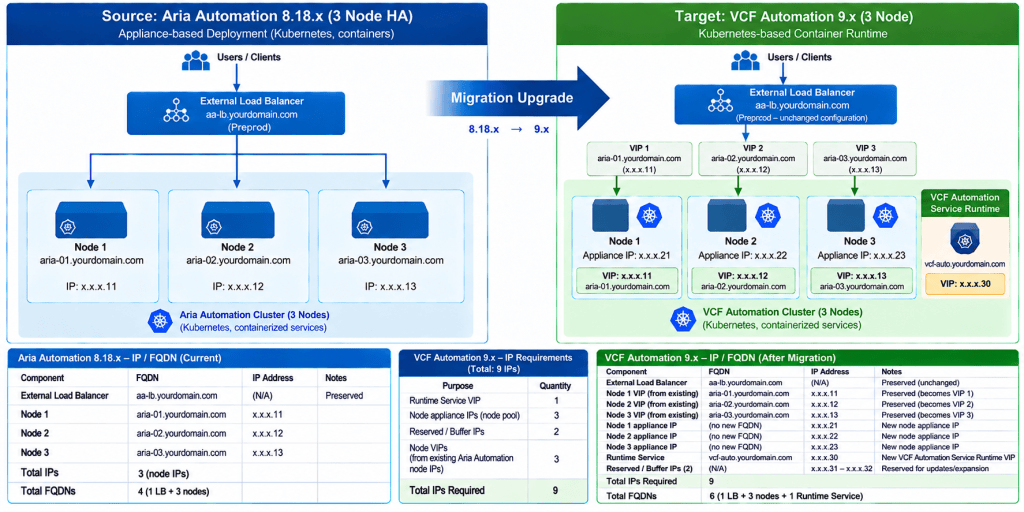
6. Upgrade Scenario: Aria Automation 8.18.x to VCF Automation 9.x
When performing an in-place upgrade from Aria Automation 8.18.x to VCF Automation 9.x, the underlying architecture shifts from a legacy deployment model to a Kubernetes-based container runtime cluster integrated with VCF Management Services. Understanding the precise IP address and FQDN requirements is critical for planning subnet allocations and avoiding deployment validation failures.
IP Address Breakdown (Total: 9 IPs Required)
- 1 x VIP for Automation Runtime Service Platform: Serves as the primary Virtual IP endpoint for management and runtime control plane traffic.
- 3 x Active Node IPs: Assigned directly to the three appliance virtual machines hosting the Kubernetes container runtime cluster.
- 2 x Reserved / Buffer IPs: Kept in reserve within the subnet pool to allow non-disruptive rolling updates, node redeployments, and day-2 cluster expansions.
- 3 x Per-Node VIPs: Individual Virtual IPs allocated per node for local ingress routing, health probing, and external load balancer targeting.
FQDN Requirements (Total: 2 FQDNs)
- 1 x Runtime Service FQDN: Mapped to the main Automation Runtime Service VIP to handle machine-to-machine control plane calls and lifecycle orchestration.
- 1 x External Load Balancer / Round-Robin DNS FQDN: Configured on the external load balancer or DNS layer to distribute incoming requests across node VIPs or sites.
Discover more from VMware Cloud Foundation (VCF) Blog
Subscribe to get the latest posts sent to your email.