
Key Points
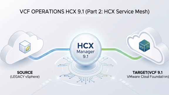
- Profile Configuration: Learn how to prepare your IP allocations and create the Network and Compute Profiles.
- HCX Service Mesh Deployment: Establish a Site Pair and deploy the Service Mesh to enable VM migrations and network extension capabilities.
About This Series
- Part 1: Deploy VMware Cloud Foundation (VCF) Operations HCX 9.1 directly from VCF 9.1 and manually deploy it on the legacy environment.
- Part 2: Creating the Network Profile, Compute Profile, Site Pair, and HCX Service Mesh.
- Part 3: Extending the networks and performing your first migration.
Watch the full video walkthrough below to see how to create the Network Profile, Compute Profile, Site Pair, and HCX Service Mesh:
Introduction
In Part 1, the HCX Managers were deployed on both the target VCF 9.1 and source vSphere environments. To complete the deployment, enable network extensions, and migrate virtual machines, additional configuration steps must be performed on both HCX Managers. This post covers the following steps:
- Network Preparation & Planning: Explaining how to prepare the IP allocations and network properties required to configure the Network Profiles.
- Network Profiles: Creating the required Network Profiles based on the IP pool allocation planned.
- Compute Profiles: Constructing the Compute Profile and assigning the Network Profiles generated in the previous step.
- Site Pair: Establishing a secure management control plane connection between both HCX Managers over TCP port 443 (SSL connection).
- HCX Service Mesh Deployment: Deploy the Service Mesh. This instantiates the HCX data plane appliances: Interconnect (IX) and Network Extension (NE) appliances to provide migration and network services.
1. Network Preparation & Planning
Before configuring the Network Profiles and deploying the Service Mesh, proper IP planning and a clear understanding of Network Profiles are fundamental. It is recommended to first review Broadcom’s official documentation on Network Profile Considerations and Concepts and the Deployment Prerequisites Checklist for further details and reference.
Take a close look at the source environment’s VMkernel adapters in Figure 1.
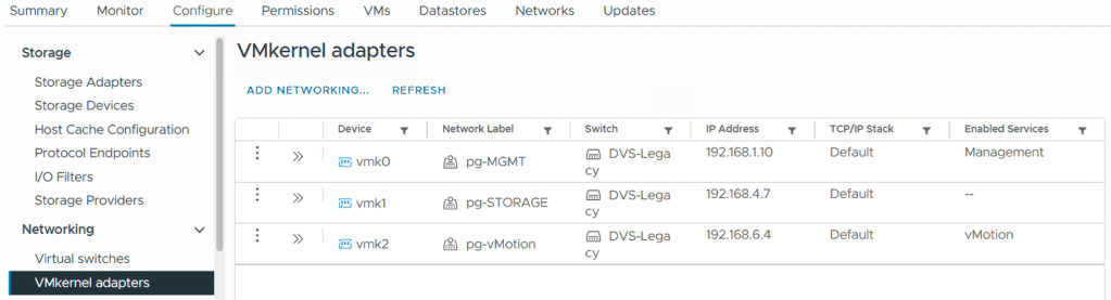
Notice that the Management interface resides on the 192.168.1.0/24 (IP address: 192.168.1.10) network, and the vMotion interface is configured on 192.168.6.0/27 (IP address: 192.168.6.4). There is also an active Storage interface (vmk1), which can be safely ignored since HCX does not use it.
Important: Note that this environment does not have a dedicated VMkernel port configured for vSphere Replication. Because a separate VMkernel port for replication doesn’t exist here, the deployment will combine both Management and Replication into a single, shared HCX Network Profile using the same subnets and the same portgroup.
Note: In the planning matrix below, the Management & Replication and vMotion rows are highlighted in red to show how they mirror this exact same network subnet configuration.
If the IP allocations for those two local profiles are examined in the table, free, unused IPs are selected inside those exact same subnets. This approach is highly recommended whenever available IP capacity exists because it dramatically simplifies the configuration. By placing the HCX appliances directly onto the existing management and vMotion networks, the need for internal routing or network firewall modifications for local traffic is completely eliminated.
The Uplink network is the only profile where routing and firewall configurations are usually required. The Uplink handles the actual transport traffic between the sites (source to VCF 9.1). The Interconnect (IX) and Network Extension (NE) data plane appliances will create the tunnel on the Uplink network. This connection between the sites is secure by default (IPSec can optionally be disabled).
Recommendation 1: Whenever possible, use free IPs within your existing local subnets for Management, vMotion, and Replication traffic. If IP space is unavailable, a different network can be created; ensure the internal infrastructure can route to them and all required firewall ports are allowed. Please consult the VMware Ports and Protocols Portal for full reference.
Recommendation 2 for MTU (Maximum Transmission Unit): Review the MTU configuration for the VMkernel interfaces assigned to your Management, Replication, and vMotion networks, and take notes. During the Network Profile configuration, you need to configure the MTU, and the MTU should match the configuration you have. For example, if you have the vmk0 as management with 9000 MTU, configure the HCX Network Profile with 9000 MTU instead of the default 1500, as this might increase replication performance.
Note: Reserving IP addresses is necessary for both the source and target VCF 9.1 environments, and respective network profiles and compute profiles will be required for both sites.
2. Building the Network Profiles
To start configuring the network profiles, access the HCX Manager interface (https://<hcx-manager-fqdn>) and log in using administrator@vsphere.local or equivalent credentials. In HCX 9.1, if configured, VCF SSO can also be utilized for authentication.
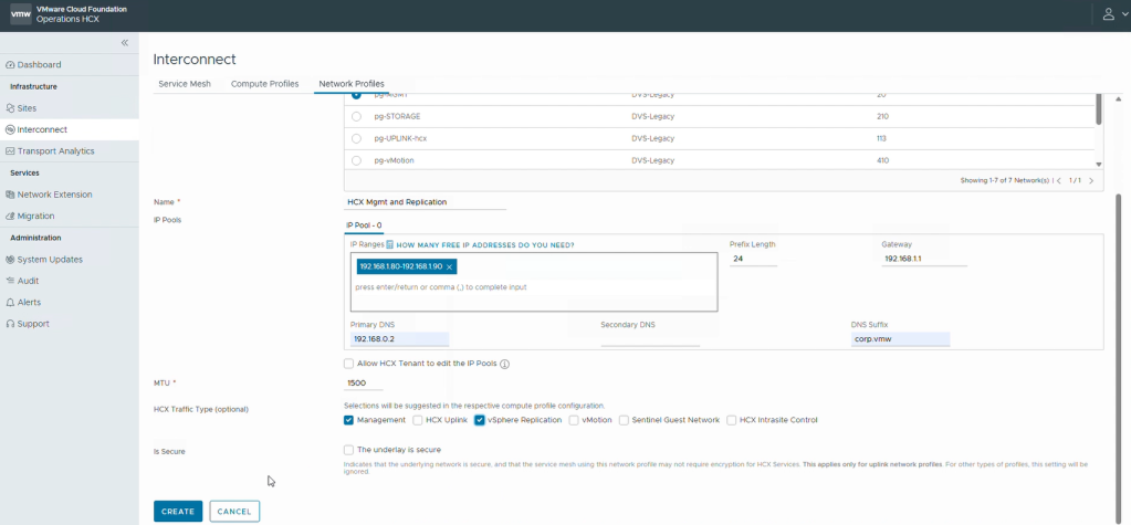
Navigate to Interconnect and click the Network Profiles tab. Click Create Network Profile to initialize the wizard. For this example, the setup begins with the management and replication profile, and the same process is then applied to the remaining profiles from the planning matrix.
Complete the wizard using these steps:
- Select the distributed port group used for management traffic, provide a name, and enter the reserved IP pool range.
Note: Ensure these IPs are free and available on the network. - Fill in the required fields for the prefix length, default gateway, MTU, and any remaining fields.
- Check both the Management and vSphere Replication checkboxes at the bottom to assign the corresponding service tags.
Note: For other networks, such as the Uplink, the specific corresponding service tag must be selected instead. - Click Create.
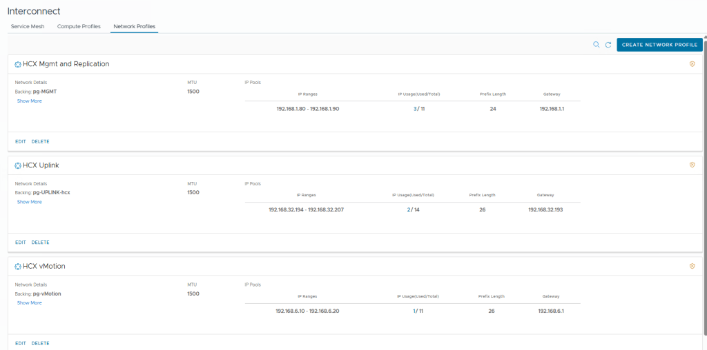
3. Building the Compute Profile
Before creating a Compute Profile, it is recommended to review Broadcom’s official documentation on Compute Profile Considerations and Concepts and Create a Compute Profile for detailed architectural guidelines.
With the network profiles successfully created, navigate to the Compute Profiles tab and click Create Compute Profile to initialize the configuration wizard.
- Provide a name for the profile and click Continue.
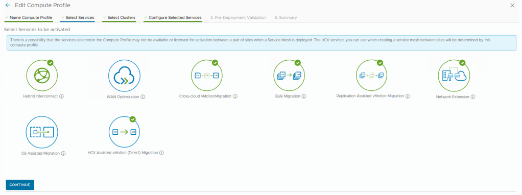
- Select the services to be activated and click Continue.
Note: Supporting primary migration types (Bulk, Replication Assisted vMotion, vMotion, and Cold Migration) requires enabling the Hybrid Interconnect, Cross-Cloud vMotion, Bulk Migration, and Replication Assisted vMotion services. If network extension is required, the Network Extension Service must also be enabled.
- In the Service Resources section, specify where the virtual machines intended for migration are currently running (defined at the datacenter, single cluster, or cluster group level).
Note: Multiple clusters can be selected, but the underlying network containers and infrastructure must be shared and accessible across all of them. Otherwise, separate compute profiles and separate service meshes are required.
- Under Deployment Resources, select the target cluster and datastore where the interconnect data plane appliances will be deployed, then click Continue.
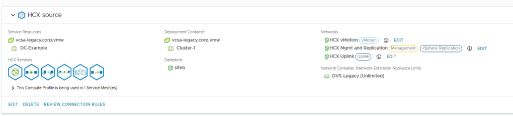
- Map the network interfaces to the profiles created in the previous section:
- Management & vSphere Replication: Review and if correct accept the auto-selected profile.
- Uplink: Select the newly built Uplink profile.
- vMotion: Confirm the auto-selected vMotion profile. If the VMkernel network is on a different subnet (routed) from the ESXi hosts, explicitly define a static route here.
- In the Network Containers stage, select the DVS or the NSX transport zone containing the port groups, VPCs, or segments intended for extension. Both the service and deployment clusters must belong to that same distributed switch or transport zone. Click Continue.
- Review the automatically generated connection rules, advance past the summary screen, and click Finish to complete the source compute configuration.
4. Establish a Site Pair
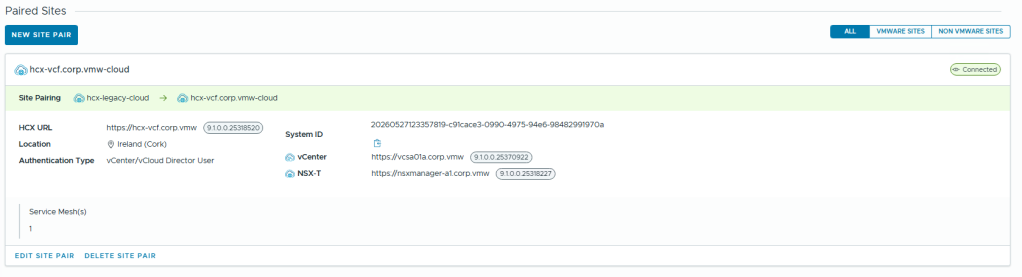
Before deploying the Service Mesh, the two HCX Managers need to authenticate and connect to each other. This critical step establishes the initial management plane control channel. For more information, access: Add a Site Pair.
Prerequisite: Before proceeding with the site pairing, you must repeat the previous steps on the destination side by creating the respective Network Profiles (NPs) and Compute Profiles (CPs) on the target HCX Manager.
Note on Direction: The Site Pair should be initiated from the source to VCF 9.1, as we are planning to migrate from the legacy vCenter to VCF 9.1, but you can also initiate a site pairing from VCF 9.1 to another instance, for example, from VCF 9.1 to VCF 9.0.
- Navigate to Sites and click New Site Pair.
- Enter the remote HCX URL of the destination environment (the target VCF 9.1 environment).
- Provide the administrative credentials for the destination environment (e.g.,
administrator@vsphere.local) or VCF SSO, and click Create.
5. Service Mesh Deployment
Once all steps are completed, including the Network Profiles and Compute Profiles on both sites, and the established Site Pair, the Service Mesh can be deployed. For more details, consult Broadcom’s official documentation on Create a Service Mesh for vSphere-Based Site Pairs.
Navigate to Interconnect, select the Service Mesh tab, and click Create Service Mesh to launch the final deployment wizard.
- Select the paired source and destination sites, choose the matching source and remote target compute profiles, review the services to be activated, and click Continue.
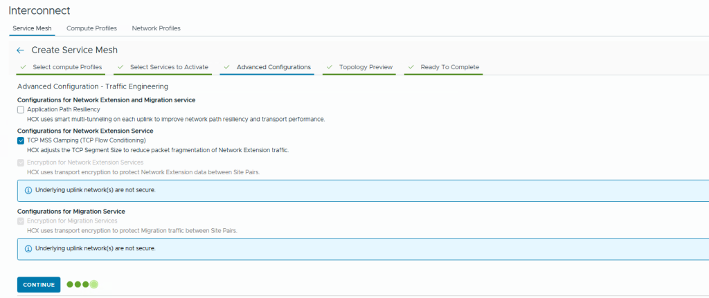
- Configure the advanced wizard parameters as required:
- Uplink Profiles & Path MTU: Overrides are optional. If the existing profile values are correct, leave them at their defaults and click Continue.
- Network Extension Scale Out: Define the Appliance Count, Mode, and DHCP profile. For HCX Network Extension High Availability (HA), a minimum of two appliances is required.
- Traffic Engineering: TCP MSS Clamping is enabled by default. Activating advanced features like Application Path Resiliency will require opening additional ports on the firewall.
- Encryption: If the This is a secure network option was not selected while creating the Uplink profile, the encryption can’t be disabled. To disable encryption, the original Uplink profile must be updated first. Click Continue.
- Review the generated Topology Preview and click Continue.
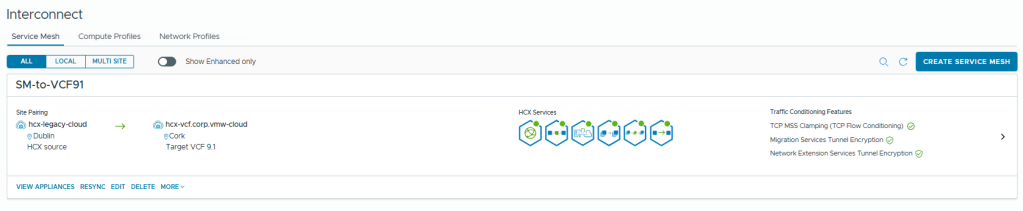
- Provide a name for the Service Mesh configuration and click Create Service Mesh.
Note: This name will be used as the prefix for the IX and NE VM names that will be created in your vCenter inventory, such as<sm-name>-IXE-I1. Keep it short and clean.
Once the Service Mesh deployment starts, the creation progress can be monitored directly from the Task menu.
What’s Next?
Congratulations! The HCX data plane is now fully established between your legacy vCenter and your new VCF environment.
In Part 3: Extending the networks and performing your first migration, we will extend our networks and perform our very first workload migration.
Acknowledgements
Special thanks to Chris O’Sullivan, Ciara Conlon and Jose Gonzalez Cobo (Product Management).
Discover more from VMware Cloud Foundation (VCF) Blog
Subscribe to get the latest posts sent to your email.