

Part 1 of a series on VKS Multiple Networks in VCF 9.1
TL;DR: VMware Cloud Foundation (VCF) 9.1 and vSphere Kubernetes Service (VKS) 3.6 introduce declarative multi-NIC support for Kubernetes nodes, making VKS multi-network support a first-class platform capability. This first post covers the foundation: provisioning a secondary NIC on every node. By itself this does not reroute application traffic; it creates the network topology that makes VKS network isolation possible and unlocks further capabilities covered in subsequent posts. Supported on NSX Virtual Private Cloud (VPC) and Virtual Distributed Switch (VDS).
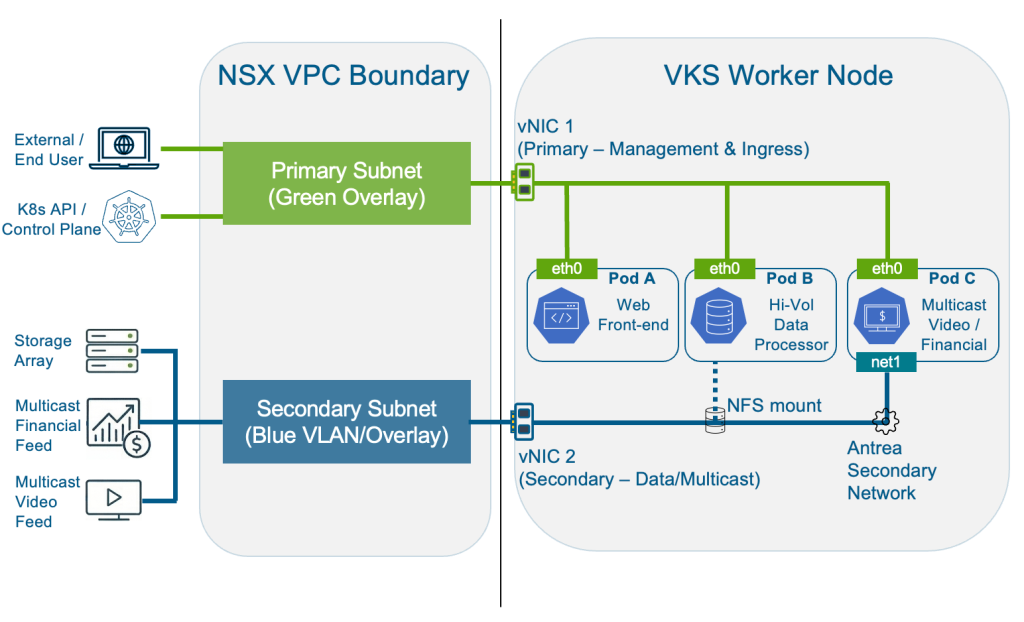
This diagram shows the VKS multi-network architecture this series builds toward. Part 1 covers the node-level vNIC separation at the foundation. With that in place, subsequent posts cover the use cases this unlocks: NFS storage isolation, pod-level multi-NIC with Antrea, multicast traffic separation, and SR-IOV (Single Root I/O Virtualization).
The Network Separation Challenge in Kubernetes
In most Kubernetes deployments, a single network interface carries all traffic: communications to the Kubernetes API server, application traffic, storage I/O, and cluster management all share eth0. That creates a potential structural compliance gap.
Frameworks including CIS Kubernetes Benchmark, NIST SP 800-190, and PCI-DSS require network segmentation. NetworkPolicies provide Layer 4 controls within the cluster, but cannot enforce separation at the node NIC level or govern traffic originating outside the cluster. The boundary needs to exist at the infrastructure layer.
VCF 9.1 addresses this directly with native multi-network support for VKS.
How VKS Multi-Network Works: Primary and Secondary NICs
VKS 3.6 introduces a first-class concept of primary and secondary node network interfaces, each with a distinct role in achieving VKS network isolation.
The primary interface (eth0) is the cluster’s backbone. It carries load balancer traffic, Kubernetes service discovery, pod-to-pod communication, and all control plane management. Critically, the primary network is immutable: set at cluster creation, it cannot be changed. This is by design. Changing the management network of a live cluster is a destructive operation.
The secondary interfaces (eth1 through eth9) are optional and purpose-driven. Secondary interfaces can be added after cluster creation and can be overridden per node pool, making heterogeneous clusters where different racks or storage tiers use different networks entirely practical.
With VKS 3.6, network topology is expressed as a single networks variable in the cluster spec and managed through the same lifecycle that manages the cluster itself. That is what “declarative” means here: your network segmentation lives in YAML alongside your cluster definition, enforced automatically on every node.
One important thing to understand before diving into configuration: adding a secondary NIC does not automatically reroute application traffic. Pods continue to use eth0 for all traffic by default. eth1 has no default route; nothing flows through it until you explicitly configure a purpose for it. The security value is topological: the Kubernetes API server only listens on eth0’s subnet. If eth0 is on a restricted management network and eth1 is on a different subnet, the control plane is physically unreachable from anything connected only to eth1. NetworkPolicies can be misconfigured or bypassed; a separate subnet backed by firewall rules at the physical layer cannot.
Think of this post as describing how to lay the cable for VKS multi-network support. The rest of the series covers what you plug into it.
The feature works across two networking backends, with different API objects for each:
| Backend | Network Provider | API Group | Object Types |
| NSX VPC | NSX_VPC | crd.nsx.vmware.com/v1alpha1 | SubnetSet, Subnet |
| VDS | VSPHERE_NETWORK | netoperator.vmware.com/v1alpha1 | Network |
Note: NSX-T T1 (the legacy NSX topology without VPC) is not currently supported.
Step-by-Step: Configuring VKS Multi-Network Support (NSX VPC)
For node-level traffic isolation (the focus of this post), the Supervisor Admin does all the work. VKS Cluster Admin and application-level personas come into play in the follow-on posts when we configure pods to actually use the secondary network.
Step 1: Supervisor Admin – Prepare the VPC Network
Before creating the cluster, create a Subnet that will back the node’s secondary vNIC. Two settings are non-negotiable: DHCP must be deactivated, and static IP allocation must be disabled. The reason is IP exhaustion. If static allocation is enabled, every time a node scales out, the subnet allocates IPs that are never fully claimed. At scale, you run out.
|
1 2 3 4 5 6 7 8 9 10 11 12 |
apiVersion: crd.nsx.vmware.com/v1alpha1 kind: Subnet metadata: name: secondary-node-net namespace: vks-ns spec: accessMode: Private # Private keeps secondary node IPs off the external network subnetDHCPConfig: mode: DHCPDeactivated # Required: secondary NICs manage their own IPs advancedConfig: staticIPAllocation: enabled: false # Required: prevents IP exhaustion at scale |
If you are creating the subnet through VCF Automation’s user interface rather than kubectl, the equivalent settings look like this: the two critical fields are Static IP Allocation: No and DHCP: None
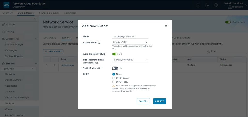
The warning the UI shows (“No IP Address Management is defined for this Subnet. It will not allocate IP addresses to connected workloads.”) is intentional; nodes get their IPs from NSX and CAPV at provisioning time, not from DHCP.
Optionally, if you need globally routable node IPs on the primary interface as well (rather than the auto-created private SubnetSet), create a SubnetSet with accessMode: Public. VKS will use it for eth0 if you reference it in the networks.interfaces.primary field.
Step 2: Supervisor Admin – Create the VKS Cluster
The entire multi-network configuration lives inside the networks variable in the cluster topology. The snippet below shows the relevant section; the rest of the cluster spec (clusterNetwork, topology class, storageClass, vmClass) follows the standard pattern.
|
1 2 3 4 5 6 7 8 9 10 11 12 13 14 15 16 17 18 19 20 21 22 23 24 25 26 27 28 29 30 31 32 |
apiVersion: cluster.x-k8s.io/v1beta2 kind: Cluster metadata: name: prod-cluster namespace: vks-ns spec: topology: class: builtin-generic-v3.6.0 controlPlane: replicas: 3 variables: - name: storageClass value: <your-storage-profile> - name: vmClass value: best-effort-medium - name: networks value: interfaces: # primary omitted: see note below secondary: - name: eth1 mtu: 1500 # Set to 9000 for jumbo frames (NFS/storage workloads) network: apiVersion: crd.nsx.vmware.com/v1alpha1 kind: Subnet name: secondary-node-net # The Subnet created in Step 1 version: v1.35.0---vmware.2-vkr.4 workers: machineDeployments: - class: node-pool name: workers replicas: 3 |
Note: Two things worth knowing about the networks variable. First, the primary field can only reference a SubnetSet (not an individual Subnet), while secondary interfaces can reference either. Second, for most deployments, omit primary entirely. VKS auto-creates a private SubnetSet for eth0, which is the right default for an internal management network. Only specify primary if you need globally routable node IPs on eth0; in that case, create a SubnetSet with accessMode: Public beforehand and reference it there.
Step 3: Verify the Configuration
Once the cluster is running, get your node names first:
|
1 |
kubectl get nodes |
Then open a shell on each node. VKS namespaces default to the restricted Pod Security Standard which blocks node debugging, so target kube-system which runs as privileged:
|
1 |
kubectl debug node/ -it --image=nicolaka/netshoot -n kube-system -- bash |
Once inside, run:
|
1 |
ip addr |
Look at interfaces 2 and 3 (eth0 and eth1). You should see each on a distinct subnet with no shared gateway:
|
1 2 3 4 |
2: eth0: <BROADCAST,MULTICAST,UP,LOWER_UP> inet 172.30.0.68/27 ... ← primary (management) 3: eth1: <BROADCAST,MULTICAST,UP,LOWER_UP> inet 172.30.0.99/28 ... ← secondary (workload/storage) |
Type exit when done; the debug pod cleans itself up automatically.
Note: eth1 has no default route and carries no traffic until you explicitly configure a purpose for it. All standard traffic continues to use eth0. If you need eth1 to reach a remote subnet (for example, an NFS storage network), you will add static routes – covered in Part 2 of this series.
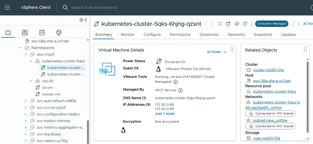
Alternatively, you can confirm the secondary NIC assignment without kubectl at all. In vSphere, navigate to your cluster’s Node Network section. You will see eth1 listed with its connected subnet. In vSphere Client, open the worker VM and check IP Addresses. Both the primary and secondary IPs appear there.
VDS Variant: VKS Multi-Network Support without NSX
The node-level secondary NIC pattern for VKS network isolation works identically on clusters backed by vSphere Distributed Switch networking. The only difference is the API group and object kind used to reference the network.
Before creating the cluster, configure the distributed port group to use trunk mode and enable both Forged Transmits and MAC Learning Policy. Missing either of these silently breaks secondary NIC connectivity for pods later; Antrea’s OVS bridge requires MAC learning to function correctly.
|
1 2 3 4 5 6 7 8 9 10 |
- name: networks value: interfaces: secondary: - name: eth1 mtu: 1700 network: apiVersion: netoperator.vmware.com/v1alpha1 kind: Network name: workload-trunk-portgroup # The VDS port group name in the namespace |
Note: Primary network customization is not supported on VDS; eth0 always uses the default namespace Network. For secondary interfaces, the name field simply references the port group by name. There are no VLAN IDs in the cluster spec. All VLAN configuration is done on the port group in vSphere before the cluster is created.
What’s Not Supported (Yet)
This is a first-generation implementation and there are meaningful gaps worth knowing before you design around this feature.
- No LoadBalancer service on secondary networks. Service type LoadBalancer always provisions on the primary network. If your ingress controller needs to expose a LoadBalancer IP on a specific secondary subnet, that is not currently possible.
- No NetworkPolicy or SecurityPolicy on secondary interfaces. Antrea network policies do not yet apply to secondary NICs. Traffic on eth1 and above is unfiltered at the Kubernetes policy layer.
- Primary NIC is permanent. The primary network cannot be changed after cluster creation. Plan your subnet carefully.
- Secondary interfaces are additive only. Once you add eth1, you cannot remove it. You can update its configuration, but removing it entirely requires destroying and recreating the cluster.
- SR-IOV VLAN tagging is VDS only. SR-IOV with VLAN tagging is not yet supported on NSX VPC.
- No Windows node pools. Windows worker nodes cannot use secondary NICs in this release.
Gotchas When Configuring VKS Multi-Network Support
These are the issues most likely to cost you time during initial setup.
1. staticIPAllocation.enabled: false is required, not just a recommendation. If static IP allocation is enabled on the parent subnet backing the secondary node vNIC, each new node will consume a statically allocated IP at provisioning time. Those IPs are never released during a rolling update. On a cluster that scales frequently, you will exhaust the subnet. Set it to false from the start.
2. On VDS, all three port group settings must be correct. The distributed port group backing a secondary NIC must have trunk mode, Forged Transmits, and MAC Learning all enabled simultaneously. You can set two out of three and the node will come up healthy, but the failure only manifests when pod secondary NICs are created and cannot communicate. There is no event or error that points directly to the port group configuration, so this tends to be a long debugging session.
Frequently Asked Questions
How do I verify that multi-network support is available in my environment?
Query the supports_vks_multi_networks capability flag on the Supervisor. Its activated field is true only when all dependencies are met: VKS 3.6+ is registered, and either supports_multiple_vds_networks (VDS) or supports_shared_subnets_with_namespace (NSX VPC, requires Kubernetes 1.30+) is enabled. VCF Automation reads this flag before surfacing multi-network options in its UI.
Can I add a secondary NIC to a cluster that already exists?
Yes. Update the networks.interfaces.secondary list in the cluster spec and VKS applies the change via a rolling node update with no cluster-wide downtime. You cannot remove an interface once added, or change the primary network on an existing cluster.
This is also easy to apply via the UI in VCF Automation. Simply edit the node network of the existing cluster.
What is the difference between a node secondary NIC and pod multi-NIC?
A node NIC is infrastructure-level: every pod on that node shares the same physical interface. Pod multi-NIC goes further: individual pods get their own dedicated interface and a unique IP from an Antrea IPPool via a NetworkAttachmentDefinition. Use node NICs for node-wide traffic separation; use pod multi-NIC when specific workloads need their own isolated network path. See Part 3 for the full walkthrough.
Do I need Antrea for node-level VKS multi-network support to work?
No. The node secondary NIC is managed by CAPV and vm-operator at the infrastructure layer, independent of CNI. Antrea is only required for pod-level multi-NIC, which uses the AntreaIPAM and SecondaryNetwork feature gates.
Up Next: The VKS Multi-Network Series
You now have a VKS cluster where every node has a secondary NIC connected to a dedicated subnet, with the management plane topologically isolated, and eth1 is ready for a purpose. The rest of the series builds on this foundation:
- Part 2 – NFS Storage Isolation: Static routes and jumbo frames on eth1 to keep storage I/O off the management network.
- Part 3 – Pod-Level Multi-NIC with Antrea: AntreaIPAM and NetworkAttachmentDefinition for per-pod interface isolation.
- Part 4 – Multicast with VLAN Extension Subnets: Bridging pods to external physical VLANs without traversing the NSX Edge.
- Part 5 – SR-IOV on VKS: SR-IOV Virtual Functions passed directly to pods for telco and HPC (high rupturing capacity) workloads on VDS.
Related Resources
- Deploy Modern Apps Faster, Scale Smarter, and Lower Your TCO with VMware vSphere Kubernetes Service in VCF 9.1
- VMware vSphere Kubernetes Service 3.6: Making Enterprise Kubernetes Safer, More Flexible, and Easier to Operate
Discover more from VMware Cloud Foundation (VCF) Blog
Subscribe to get the latest posts sent to your email.


